Overview of parts
A Part is a Role or an Attribute (untyped or with a Basic Type, Class, Data Type, Interface, Signal or Type Definition set as its data type) in the context of a top-level Class, Data Type, Interface or Signal, and its contained Parts and Ports.
Each Part that does not use a Basic Type or Type Definition as its type can contain many Parts and Ports, and so on. A Part that uses a Basic Type or Type Definition cannot contain Parts or Ports.
When a Role or Attribute represents a Part, its symbol in a Modeler pane is as follows:
 Aggregate Role or Attribute that is untyped or uses a Basic Type, Class, Data Type, Interface, Signal or Type Definition as its data type.
 Non-aggregate Role.
In the Packages and Parts pane, a Part's name is shown as follows:

A Part appears on a Composite Structure Diagram as a box or a box with a compartment. A Part has a compartment when it shows contained Parts or Ports.
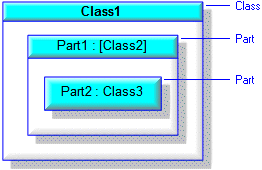
Note that if a Part contains a Part that has had its Default Value changed in context, on a Composite Structure Diagram the type of the containing Part is shown in brackets. In the preceding example, the Part2 part in context has a Default Value that is different from the Part2 part on the type, that is, the Class2.
Non-composite Parts are shown with a dashed outline.
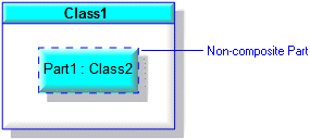
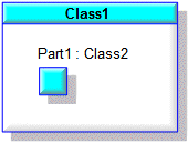
You can show a Part's Name and associated text outside of the Part through the View Options - select the Show Text As Floating Attachment check box.
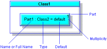
Through the View Options you can show or hide a Part's Name, Full Name, Type, Multiplicity and Default Value. In addition, you can make a Port snap to the boundary of the owning Part or Port – you can snap to the inside, middle or outside of the boundary.
Top-level Parts can be shown as frames through the Part's View Options - select the Show As Frame check box.
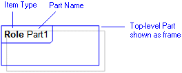
Note that the Full Name of a Part is shown only when the Part is displayed on the diagram as a top-level item.
If a Part is unnamed, the name of the Part's type is displayed in square brackets when displayed in a Modeler pane.
If a Part has no Stereotypes applied to it, you can display its type's Stereotypes on the Composite Structure Diagram.
Class, Data Type, Interface and Signal contained Parts
When a Class, Data Type, Interface or Signal contains a Part, the Part can be a Role or Attribute (untyped or with a Basic Type, Class, Data Type, Interface, Signal or Type Definition set as its data type), and the Part can be created on the Class Diagram or Composite Structure Diagram:
• On a Class Diagram, you create a Part through a Role or Attribute:
◦ By adding an Aggregation or Association (which creates a Role that is the Part) between the Class, Data Type, Interface or Signal and the Part's type.
◦ By adding an Attribute to the Class, Data Type, Interface or Signal, and then setting its Data Type to nothing or the Part's type.
• On a Composite Structure Diagram, you create a Part through the Part button:
◦ If you create a Part on a Class, Data Type, Interface or Signal that uses a Class, Data Type, Interface or Signal as its type, Modeler uses a composite aggregate Role to create the Part.
◦ If you create a Part on a Class, Data Type, Interface or Signal that is untyped or uses a Basic Type or Type Definition as its type, Modeler uses a composite Attribute to create the Part.
◦ If you create a Part on a Part or Port, Modeler uses a composite aggregate Role to create the Part.
The following example shows how a Part created from an aggregate Role appears in Modeler. Class1 has a Part (aggregate Role) named Part1 whose type is Class2. The Composite property of Part1 is derived from the Composite Aggregation property of the associated Association.

The following example shows how a Part created from a composite Attribute appears in Modeler. Class1 has a Part (composite Attribute) named Part1 whose type is Class2. The Composite check box on Part1's Property Pages is selected.

If you create a Part for a Class or Signal, that Part (and its contained Parts and Ports) are available to any Part or Port that uses the Class or Signal as its type.
Class, Data Type, Interface and Signal contained Parts are shown on the Packages pane and the Parts pane.
Part and Port contained Parts
When you create a Part for a Part or Port, you must do so through the Composite Structure Diagram: Modeler creates a typed Part as an aggregate Role, and creates an untyped Part as a composite Attribute.
The following example shows how a Part created for a Part on a Composite Structure Diagram appears in Modeler. The Part2 part has been added to Part1 part on the Composite Structure Diagram.

Note that adding the Part2 part to the Part1 part does not create a composite Aggregation between their types, that is, Class2 and Class3.
Part and Port contained Parts are shown on the Parts pane, but not the Packages pane.
Adding Parts to a Composite Structure Diagram
You can create new Parts for a Class, Data Type, Interface, Signal, Part or Port on a Composite Structure Diagram through the  Part button on the Composite Structure Diagram tab.
 Part button on the Composite Structure Diagram tab.
Through the  Part button you can also add existing Parts to a Class, Data Type, Interface, Signal, Part or Port by right-clicking the diagram item. When adding an existing Part, Modeler lists valid Parts that can be added, that is, the Parts that have previously been added to the item (Class, Data Type, Interface, Signal, Part or Port) and any Parts the item's type has.
 Part button you can also add existing Parts to a Class, Data Type, Interface, Signal, Part or Port by right-clicking the diagram item. When adding an existing Part, Modeler lists valid Parts that can be added, that is, the Parts that have previously been added to the item (Class, Data Type, Interface, Signal, Part or Port) and any Parts the item's type has.
You can show a Part on a Composite Structure Diagram as a top-level item - you do this by dragging the Part to free space on the Composite Structure Diagram. When a Part is a top-level item, you can display the Part as a frame through its View Options. Use the Parts pane to find Parts in context.
You can use the Populate Parts command on the context menu of a Class, Data Type, Interface, Signal, Part or Port to add contained Parts on a Composite Structure Diagram.
Rescoping Parts
You can rescope Parts through the Parts pane and through Composite Structure Diagrams:
• In the Parts pane, drag the Part you want to rescope to the required Class, Data Type, Interface, Signal, Part or Port.
• On a Composite Structure Diagram, drag the Part you want to rescope from the Parts pane or from the Composite Structure Diagram, and drop the Part to the required Class, Data Type, Interface, Signal, Part or Port on the diagram.
Showing contained Parts out of context
Sometimes you may want to show a Part not contained by its parent Class, Data Type, Interface, Signal or Part. In the following example, we want to show the Tire part in the Bicycle class without showing its parent Wheel part.

If we drag the Tire part to the Bicycle class, Modeler will rescope the Tire part to the Bicycle class, which is not what we want to do. To add the Tire part to the Bicycle class without rescoping it, we drag the Tire part to the Bicycle class whilst holding down the Alt key - holding down the Alt key while you drag a Part from a Modeler pane to a Composite Structure Diagram stops Modeler from rescoping that Part.

Notice that when the parent of a contained Part is not shown on the diagram, Modeler shows the full containment name of the Part - in this case 'Bicycle.Wheel.Tire'.
Redefinitions
When you create a Part, you create that Part in the context of a top-level Class, Data Type, Interface or Signal, and its parent Parts and Ports. If a Part inherits Parts or Ports from its type (a Class, Data Type, Interface or Signal), the inherited Parts and Ports are used in a different context to that of the Class, Data Type, Interface or Signal. When a Part or Port is created in a different context, Modeler creates that Part or Port as a redefinition so that you can refine it independently of the item it redefines.
Rolling up features
On a Composite Structure Diagram you can add the following features to a Part: Parts, Ports, Associations and Dependencies to Interfaces. After creating these features in the context of a Part, you can roll up the features to the Part's type (a Class, Data Type, Interface or Signal), so that the features are available to any Part or Port that uses that Class, Data Type, Interface or Signal as its type. Also, after rolling up a Part's features, those features can be shown on Class Diagrams.