Overview of objects on sequence diagrams
You can add selected object types along the top of a Sequence Diagram. Each object has a lifeline to which stimuli can be added.

You can add an object type through its associated button on the Sequence Diagram tab, or by dragging the item from an appropriate pane to the diagram.
Each object can reference a Sequence Diagram or General Flow Diagram to show part decomposition.
The order of the objects on a Sequence Diagram is not important, but you should arrange objects for maximum clarity.
You can show the interaction of the following object types.
Actor

An Actor is anything outside the system with which the system interfaces. Actors must be added to the left of the System Boundary.
Instances

Instances can be added to the left or right of the System Boundary. Typically you would not add an instance to the right of the System Boundary and to the left of the Architecture Boundary, but Modeler does not enforce this positioning. The Class, Data Type or Interface that is the Instances type can own Operations used for Operation and Return messages.
Interface Devices

An interface device is a piece of hardware that interacts with an Actor, another Subsystem or a different system entirely. Interface Devices must be added to the right of the System Boundary. You should add Interface Devices to the left of the Architecture Boundary, but Modeler does not enforce this positioning.
Packages

Packages allow you to organize items and diagrams in a model. Packages can own Operations used for Operation and Return messages.
Packages must be added to the right of the System Boundary. You should add Packages to the right of the Architecture Boundary, but Modeler does not enforce this positioning.
Part

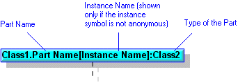
Parts can be added to the left or right of the System Boundary. Typically you would not add a Part to the right of the System Boundary and to the left of the Architecture Boundary, but Modeler does not enforce this positioning.
For a Class or Interface owned Sequence Diagram, you can drag a Class, Data Type, Interface or Signal to the diagram and Modeler will create a Part on the owning Class or Interface that uses the dragged item as its type.
When the Sequence Diagram is not Class or Interface owned, Parts can be added to a Sequence Diagram only by dragging them from an appropriate pane. Use the Parts pane to view Parts in context. When the Sequence Diagram is Class or Interface owned, Parts on the owning Class or Interface can be created through the Part button.
• A dashed outline indicates that the Part is not composite. • If no Stereotypes are applied to a Part, the Stereotypes of the Part's type are shown on the Sequence Diagram. |
Port

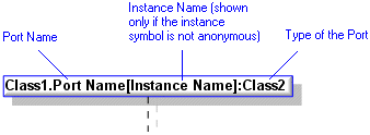
Ports can be added to the left or right of the System Boundary. Typically you would not add a Port to the right of the System Boundary and to the left of the Architecture Boundary, but Modeler does not enforce this positioning.
Ports can be added to a Sequence Diagram only by dragging them from an appropriate pane. Use the Parts tab to view Ports in context.
• A dashed outline indicates that the Port is not composite. • If no Stereotypes are applied to a Port, the Stereotypes of the Port's type are shown on the Sequence Diagram. |
Subsystem

A Subsystem contains components providing a common service.
Subsystems must be added to the right of the System Boundary. You should add Subsystems to the right of the Architecture Boundary, but Modeler does not enforce this positioning.