Creating a Callout
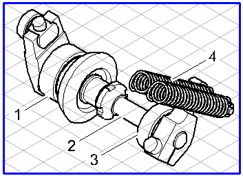
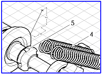
A Callout element consists of a group of three individual elements – the text element, the frame around the text element, and the leader line.
Select the
Callout
tool from the toolbox. Click on the point on the drawing area at which the callout element is to be placed or the point where it is to start. When you release the mouse button after clicking, the text element appears with the frame. If, instead of this, you click with the drawing cursor on the drawing area and drag the line as it becomes visible, you will create a callout element with leader line. Different callout styles are required for each of the two examples (see
Show Attribute Window).
Grid Alignment
The orientation of a callout element with leader line depends on whether or not
Grid Alignment is switched on when the element is created. If the
Grid Alignment function is active

, the callout element is forced into one of the three major planes of the current grid depending on the direction it is dragged in.
Without
Grid Alignment
, the callout element can be rotated freely.
This setting can be temporarily reversed by holding down the ALT key while dragging.
Grid Snap and Element Snap
Start points of leader lines can be attracted by neighboring grid or element points. Whether or not they are attracted depends on the current setting of
Grid Snap
and
Element Snap
.
The Grid Snap setting can be temporarily reversed by holding down the CTRL key while dragging.
Show Dimensions on the Element
If the
Show dimensions
option has been activated, length information is displayed for callout leader lines as they are being dragged. If the line is located on one of the major axes of the current grid or in the horizontal plane, the length of the line will be displayed. If this is not the case, two dimensions will be displayed – namely, the lengths along the two major axes involved.
Displaying Dimensions in the Dimensions Bar
The dimensions bar shows a maximum of three dimensions when a leader line is dragged. The first field shows the length of the leader line without perspective foreshortening. No dimension will be displayed if the leader line lies outside the major axes of a parallel perspective. The second field shows the actual length of the leader line, i.e. the true length. The third field indicates the orientation angle of the leader line relative to the horizontal.
 tool from the toolbox. Click on the point on the drawing area at which the callout element is to be placed or the point where it is to start. When you release the mouse button after clicking, the text element appears with the frame. If, instead of this, you click with the drawing cursor on the drawing area and drag the line as it becomes visible, you will create a callout element with leader line. Different callout styles are required for each of the two examples (see Show Attribute Window).
 tool from the toolbox. Click on the point on the drawing area at which the callout element is to be placed or the point where it is to start. When you release the mouse button after clicking, the text element appears with the frame. If, instead of this, you click with the drawing cursor on the drawing area and drag the line as it becomes visible, you will create a callout element with leader line. Different callout styles are required for each of the two examples (see Show Attribute Window).

 , the callout element is forced into one of the three major planes of the current grid depending on the direction it is dragged in.
 , the callout element can be rotated freely.
 and
and  .
. option has been activated, length information is displayed for callout leader lines as they are being dragged. If the line is located on one of the major axes of the current grid or in the horizontal plane, the length of the line will be displayed. If this is not the case, two dimensions will be displayed – namely, the lengths along the two major axes involved.
