Exercise 1: Animation for the Disassembly of Parts
1. Open the file, support_ani0.idr, from the Arbortext-IsoDraw-install-path\Tutorial\Tutorial CADprocess folder in the installation folder. Save the file as support_ani1.idr.
|
|
Before creating animations, it is important to ensure that object information has been created for each of the objects used. Object information has been assigned to all the objects in the file support_ani0.idr that has been prepared for this exercise.
|
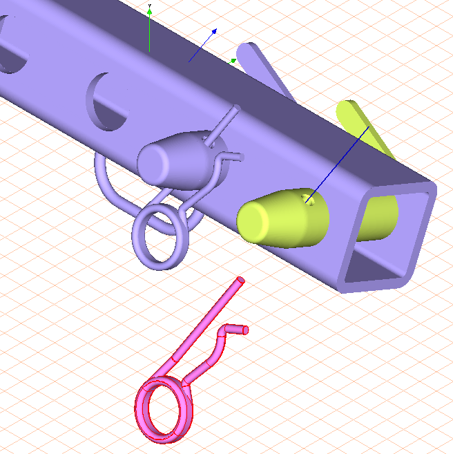
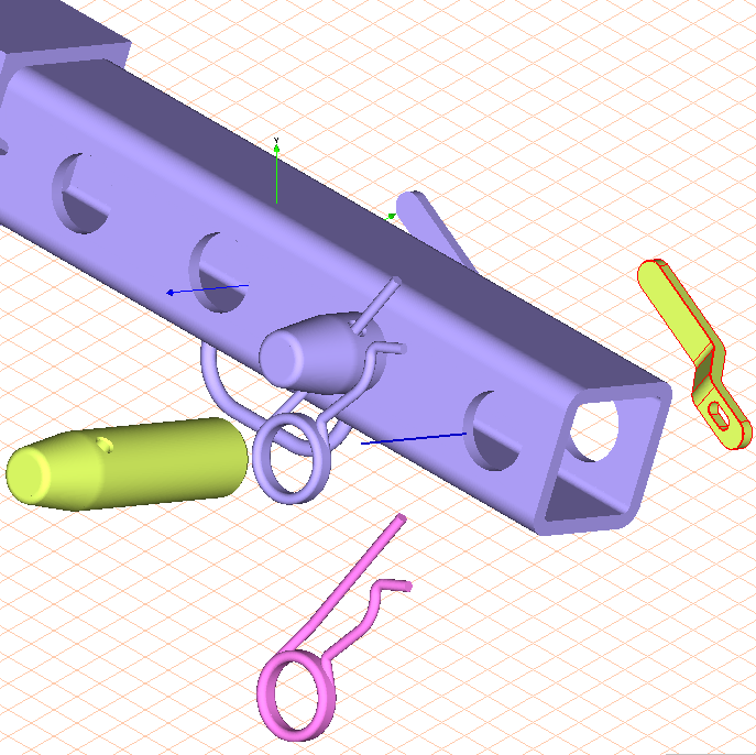
The drawing appears on the screen as indicated in the figure in Rendering display mode. The three parts to be animated are depicted in special colors. The spring plug is magenta, the bolt and lever are yellow.
The first step is to remove the spring plug from the bolt. The bolt is then withdrawn from the front of the support. The lever at the rear of the support is simultaneously removed. These are the disassembly steps to be implemented in the animation.
As the move axis for the spring plugs is outside the coordinate axes, a free move axis must be created. The two free axes in this exercise run through the center point of the bore in the bolt and through the center point of the spring plug diameter.
| When an animation is being edited with the Edit animation command, it is not possible to select a free axis. If a free axis is needed for an animation it must be defined beforehand. |
2. Click the symbol for
3D Select axis (based on a path)
.
The axis selector symbol appears next to the cursor.
3. The drawing area must be enlarged to ensure that the contour of the plug diameter can be accurately clicked.
Hold down the CTRL+ALT keys.
The cursor changes into a magnifying glass with a plus sign.
4. Double-click your mouse in the area of the spring plug.
The spring plug is now depicted larger.
5. Using the cursor, click on the contour of the diameter at the upper end of the spring plug.
After clicking, Arbortext IsoDraw CADprocess creates the free axis. It appears in the center as a blue line running perpendicular to the surface that has been clicked. The free axis is now active. The figure depicts the section of the drawing with the free axis.
6. Open the object window by selecting the > menu.
The object window is displayed with the name of the file on the drawing sheet.
7. Holding down the CTRL key, click on the + symbol in front of the file name support_ani1.idr.
All of the objects contained in the file are shown.
8. Select the button next to Name in the object window.
The Objects window will now appear as indicated below.
9. Select the > menu.
The Edit Animation and Timeline dialog boxes appear. The Edit Animation and Timeline dialog boxes contain no entries. The timeline for the current time in the Timeline window indicates 0.
10. Click on the uppermost entry in the object window, 114_spring plug....
The spring plug (114_spring_plug...) is selected.
11. The first step of the animation involves pulling (moving) the spring plug downwards and out of the bolt.
Select the > > menu.
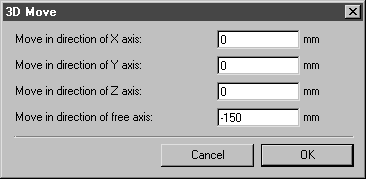
The following dialog box appears.
The spring plug is moved along the active free axis.
12. Enter the value -150 next to Move in direction of free axis. Confirm the settings by clicking OK.
This value ensures the plug is moved a sufficient distance away from the other parts.
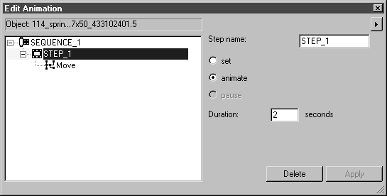
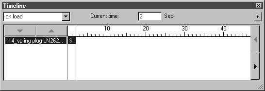
Both the Edit Animation and Timeline dialog boxes now appear as illustrated below.
In the Edit Animation dialog box, the name of the animated object – 114_spring.... – is displayed in the field at the top of the window. Below this is the entry for the first sequence with the first step. The step contains the action Move.
The name of the animated object also appears in the Timeline window. The timeline for the current time indicates 2 because the action is set to last 2 seconds. The sequence is depicted as a bar with a red S.
In the drawing, the spring plug is now depicted in the position it takes after being moved.
If you look at the 114_spring plug entry in the object window, you will notice the pen symbol for an animation behind the entry.
13. During playback, the animation is to start after a 2-second delay. The start time for the sequence must be set accordingly.
Click on the SEQUENCE_1 entry in the Edit Animation dialog box.
The sequence setting options appear in the dialog box.
14. Enter 2 in the panel next to start after and click on Apply.
15. The next animation step involves moving the bolt (102_bolt) in the direction appropriate for disassembly. To do this, a new free axis must be defined for the direction of movement.
16. To play the animation without including the particular sequence, select disabled. The details of the individual steps in the illustration are saved, but removed from the timeline.
17. End the animation by clicking the close box in the Edit Animation dialog box.
| Arbortext IsoDraw CADprocess automatically saves the animation steps that have been created so far. |
18. Click the symbol for
3D Select axis (based on a path).
The axis selector symbol appears next to the cursor.
19. Using the cursor, click on the contour of the upper diameter of the bolt.
After clicking, Arbortext IsoDraw CADprocess creates the free axis. It appears in the center as a blue line running perpendicular to the surface that has been clicked. The free axis is now active. The figure depicts the section of the drawing with the free axis.
20. Select the > menu again.
The Edit Animation and Timeline dialog boxes appear. The Edit Animation dialog box appears with no entries. The timeline for the current time in the Timeline window indicates 4. This is the point in the timeline when the spring plug animation ends. This is also the point in the timeline when the bolt animation is to begin. The selected time is therefore set accordingly.
21. Click the entry 102_bolt situated lower down the list in the object window.
The bolt (102_bolt) is selected.
22. The animation step is to pull (move) the bolt forwards and out of the tube (101_tube).
Select the > > menu.
The following dialog box appears.
The bolt is moved along the active free axis.
23. Enter the value 380 next to Move in direction of free axis. Confirm the settings by clicking OK.
This value ensures that the bolt is moved a sufficient distance away from the other parts.
Both the Edit Animation and Timeline dialog boxes now appear as illustrated below.
In the Edit Animation dialog box, the name of the animated object – 102_bolt...– is displayed in the field at the top of the window. Below this is the entry for the first sequence with the first step. The step contains the action Move.
The name of the animated object also appears in the Timeline window. The timeline for the current time indicates 6 because the action began at the current time 4 (seconds) and is set to last 2 seconds. The sequence is depicted as a bar with a red S.
In the drawing, the bolt is now depicted in the position it takes after being moved. The spring plug is also depicted in its disassembled position as this animation has already been executed.
If you look at the 102_bolt entry in the object window, you will notice the pen symbol for an animation behind the entry.
24. The last part still to be moved to its disassembly position is the lever (9515103301.1). The lever is moved along the same axis as the bolt. The free axis is still active.
In the animation, the lever is to be moved in tandem with the bolt. To do this, the current time for the beginning of the animation must be set to the same time as the beginning of the bolt animation. The bolt animation starts at 4 seconds.
Move the timeline in the Timeline dialog box to 4 or enter 4 next to Current time.
25. Click the entry 9515103301.1 underneath the bolt that has already been animated (102_bolt) in the object window.
The lever (9515103301.1) is selected.
26. The animation step involves moving the lever backwards away from the tube (101_tube).
Select the > > menu.
The following dialog box appears.
The lever is moved along the active free axis.
27. Enter the value -100 next to Move in direction of free axis. Confirm the settings by clicking OK.
This value ensures that the lever is moved a sufficient distance away from the other parts.
Both the Edit Animation and Timeline dialog boxes now appear as illustrated below.
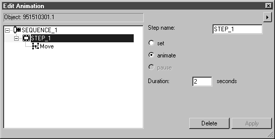
In the Edit Animation dialog box, the name of the animated object – 9515103301.1– is displayed in the field at the top of the window. Below this is the entry for the first sequence with the first step. The step contains the action Move.
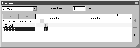
The name of the animated object also appears in the Timeline window. The timeline for the current time indicates 6 because the action began at the current time 4 (seconds) and is set to last 2 seconds. The sequence is depicted as a bar with a red S.
In the drawing, the lever is now depicted in the position it takes after being moved. The spring plug and bolt are also in their disassembled positions as these animations have also been executed.
If you look at the 9515103301.1 entry in the object window, you will notice the pen symbol for an animation behind this entry also.
28. This completes the animation. No doubt you are now curious to see what the animation looks like when played back.
Click the close box of one of the two dialog boxes you used to create the animation.
29. Save the file.