Commands for Editing Grids
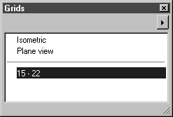
To edit a grid, click on the arrow in the right-hand corner of the window and select one of the two commands from the pop-up menu. When you select a command, a dialog box appears. The dialog boxes for New grid and Edit grid are structured in the same way. The only difference is that, for the New grid window, an entry box appears for the name, whereas for the Edit grid window, the name of the current grid is already entered.
The Edit grid dialog box also appears if you double-click on the name in the Grids window.
Edit Grid
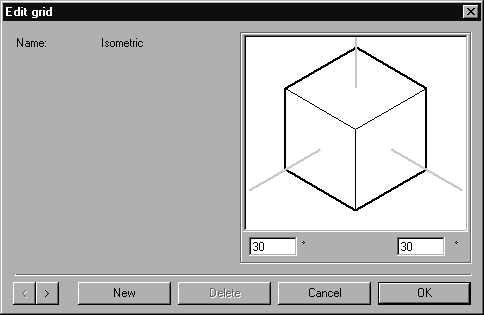
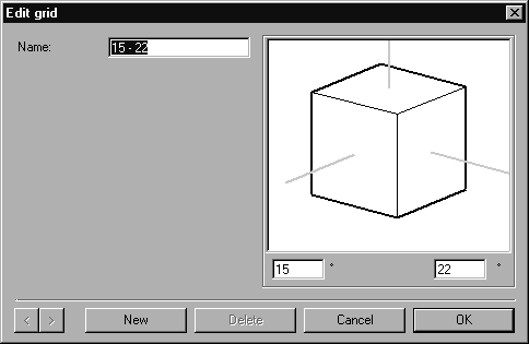
To edit a grid, select the command Edit grid. The following dialog box opens:
The current values of the grid are displayed in this window. It is possible to change these values, to add new grids and also to delete existing grids.
Name
Each grid must have an unambiguous name. It is not possible to change the names of the Isometric and Plane view standard grids.
Angle
Enter the angles you require for the major axes. Use the cube to check whether the result is correct.
Paging
Clicking one of the two arrow buttons

allows you to page through the list of available grids.
New
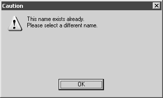
Selecting New creates a new grid. As default values, the new grid receives the angles of the last grid to be displayed and a name which is made up from the rounded angle values (e.g. 30 – 30). You may of course change these preferences. If a grid with that name already exists, the following warning window appears:
Confirm with OK and change the name. You can now change the settings as required.
Delete
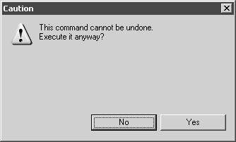
Clicking Delete removes a grid. Deleting a grid cannot be undone. Consequently, the program will ask you for confirmation:
Click Cancel if you do not want to make the changes. Click OK to delete the grid with immediate effect. The standard grids Isometric and Plane view cannot be deleted.
Quitting the Dialog Box
As long as the dialog box is displayed, all changes made to existing grids including the new creation or deletion of grids are not yet saved. These changes only take effect after you have quit the dialog box by clicking OK. Clicking Cancel undoes all the changes you have made.
New Grid
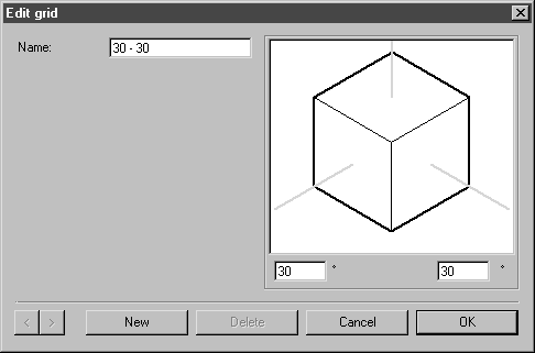
This command allows you to create a New grid for the current file. If you select this command, the following dialog box will appear:
Name
The suggested Name is composed from the angles of the two major axes. It is possible to change this name.
Angle
The angles of the current grid are specified as default values here. Enter the angles you require for the major axes and use the cube to check whether the result is correct.
New
Clicking New allows you to create further grids.
Quitting the Dialog Box
Click OK to confirm newly created grids, click Cancel to quit the dialog box without creating new grids.
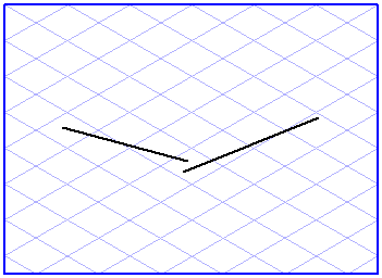
You can also create a new grid by drawing two lines. These lines define the two major axes of the new grid, the X and Y axes.
Select the two lines and then call up the New grid command. The familiar dialog box appears:
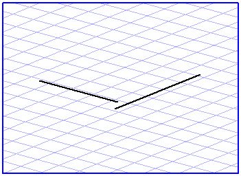
Arbortext IsoDraw automatically calculates the angles of the two major axes. The name it suggests for the new grid is made up of rounded values of these two angles.
Clicking OK creates the new grid which then appears in the list in the Grids window. Clicking its name makes it become the active grid.
| This method provides you with a quick and convenient way of creating new perspective grids when tracing scanned drawings, for example. Drag two lines in the direction of the relevant major axes, select them and create a new grid. |