About Contour Sets
A contour set is a named collection of 3D objects, such as parts in a subassembly, that are highlighted with the same color when you project them to 2D. The highlight is a flat-shaded color fill inside each object’s projected 2D contour.
|
|
If the CAD file you place in Arbortext IsoDraw has colored parts or assemblies, you can create contour sets with fill colors that match the part or assembly colors in the CAD file.
|
A contour set contains one or more 3D objects. You create contour sets in 3D mode for display in 2D.
Use the Contour Sets attribute window in 3D mode to create and edit contour sets. In the 3D Projection-Set dialog box, select the create contour fills check box to show all contour sets filled with their colors in 2D.
In 3D mode, click > to preview contour sets as they will appear in 2D.
Create Contour Fills
Select the create contour fills check box under remove hidden lines to create a closed, filled Bézier path around the outer contour of the 3D set. To see the filled contour path in 2D mode after 3D projection, turn on Preview. (From the Window menu, point to Preview and then click Preview.)
The 3D set contour path is filled with a single color (white by default) and its outline is invisible. (The outline Pen attribute is set to No pen.)
To change the contour fill color for the 3D set you are projecting with remove hidden lines selected:
1. Verify that the create contour fills check box under remove hidden lines is selected.
|
|
If the create contour fills check box is cleared, you will not be able to change the color.
|
2. Click the Options button.
3. In the
Options-
Set dialog box, select a color under
Fill contour with color and then click
OK. (See the color selection instructions under
Fill contour with color in
3D Projection Options – Remove Hidden Lines .)
You can also change the 3D set contour fill color, and other 3D projection options, in the 3D Options preferences panel. Like other 3D Options preference settings for 3D projections, the scope of this contour fill color setting (specifically, which 3D set, or 3D sets, it applies to) depends on the state Arbortext IsoDraw CADprocess is in when you change the preference setting. (See Setting Contour Fill Color as a 3D Options Preference for 3D Projections.)
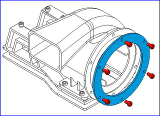
Example: 3D Set Contours with Different Colors
The example remove hidden lines illustration below has 3D set contours that are filled with different colors. This section describes how it was created.
Three 3D sets were used to create this illustration: One for the blower assembly, one for the flange (blue), and one for the six flange bolts (red).
The blower assembly 3D set was projected first without a filled contour. Next, the flange 3D set was projected with a blue-filled contour. Last, the 3D set containing the six bolts was projected with a red-filled contour.
The detailed steps used to create this example illustration are listed below for reference. Substitute your assemblies and parts for the blower assembly, flange, and bolts in these steps to create similar illustrations with color-filled 3D set contours.
1. Open (or Place) the 3D CAD file for the assembly in Arbortext IsoDraw CADprocess.
2. Prepare the view for 3D projection. In this example:
a. On the
3D Tools toolbar, click the
Isometric view top
button.
b. Right-click the flange and click Move. Move the flange +10 mm in the Z-axis direction.
c. Select the flange bolts.
d. Right-click one of the selected bolts and click Move. Move the bolts +20 mm in the Z-axis direction.
3. On the
3D Tools toolbar, click the
Convert to 2D illustration
button.
4. In the 3D Projection-Set dialog box, click remove hidden lines and clear the create contour fills check box.
5. Click OK to perform the 3D projection. In 2D mode, the assembly is shown with hidden lines removed and no filled contours.
6. Next, Place the flange and project it into 2D with a blue-filled contour:
a. Place the 3D CAD file and prepare the view as described in Steps 1 and 2 above.
b. Delete all the objects in 3D mode except the flange object.
c. Click the
Convert to 2D illustration button in the
3D Tools toolbar.
d. In the 3D Projection-Set dialog box, click remove hidden lines and select the create contour fills check box.
e. Click the Options button.
g. Click OK to perform the 3D projection. In 2D mode, the blue flange is displayed in front of the assembly.
7. To finish, Place the flange bolts and project them into 2D with their contours filled with red:
a. Repeats Steps 6(a.) through 6(g.) with these exceptions:
▪ In Step 6(b.), delete all the objects except the flange bolt objects.
▪ In Step 6(f.), select red for the contour fill color.
b. In the 3D Projection-Set dialog box, click OK to perform the 3D projection. In 2D mode, the red bolts are displayed in front of both the assembly and the blue flange.
Setting Contour Fill Color as a 3D Options Preference for 3D Projections
You can set the contour fill color (…and other 3D projection settings) on the 3D Options preferences panel. Consider setting this preference for one or all 3D sets in the following cases:
You always use the same contour fill color for:
• Case 1: A particular 3D set you project in multiple illustrations during an Arbortext IsoDraw CADprocess application session.
• Case 2: All 3D sets you project in one illustration.
• Case 3: All 3D sets you project in all illustrations.
To make a contour fill color preference setting (…or any other 3D projection setting) the default in each case above:
• Case 1: Set the preference in 3D mode with the 3D set active. This makes your setting the default whenever you project that particular 3D set during the current Arbortext IsoDraw CADprocess application session. If you exit and then restart the application, the default preference setting no longer applies to that particular 3D set.
• Case 2: Open the illustration file and set the preference in 2D mode. This makes your setting the default for all 3D sets you project in that illustration file. The default setting persists for that illustration file when you close and reopen it, and when you exit and restart the application.
• Case 3: Close all illustration files and then set the preference. This makes your setting the default for all 3D sets you project in all illustration files. The default setting persists for all illustration files when you close and reopen them, and when you exit and restart the application.
To set the contour fill color preference for one or all 3D sets (depending on the case above):
1. Select > and then select 3D Options…
◦ Case 1: …in 3D mode with the 3D set active.
◦ Case 2: …with the illustration file open in 2D mode.
◦ Case 3: …with all illustration files closed.
2. In the 3D Options preferences panel, click the 3D Options button to open the 3D Projection-Set dialog box (or 3D Projection-Set dialog box for Case 1.)
3. Click remove hidden lines and select the create contour fills check box, and then click the Options button.
4. In the
Options dialog box (or
Options-
Set dialog box for Case 1) under
Fill contour with color, select the color. (See color selection instructions under
Fill contour with color in
3D Projection Options – Remove Hidden Lines .)
5. Click OK twice to close the dialog boxes, and then click OK to close the Preferences dialog box. The fill color preference setting is applied to the 3D set or 3D sets (depending on the case above).
About Editing 3D Set Contour Paths in 2D Mode
In 2D mode, the filled contour path is grouped with the 3D set. Use the
Arrow (+)

tool to select the contour path for editing while the 3D set is grouped. Or, you can ungroup the 3D set and then edit the path shape or fill color as you would any other filled Bézier path.
| Ungrouping a placed 3D set breaks the link to its source 3D data. |
The contour path is a single path around the outer contours of all objects in the 3D set. It is not a compound path, however. So, if the 3D set includes objects with holes (such as the flange in the example above) or multiple, separate objects (such as the bolts in the example above), the path will have connecting lines between distinctly separate parts of the contour. If you make the contour outline visible by applying a different Pen attribute, you may have to edit the path to remove these connecting lines.