Shaft Segment – Gear Wheel
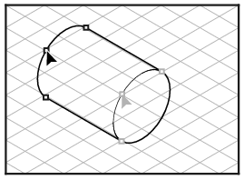
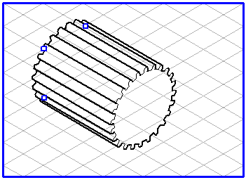
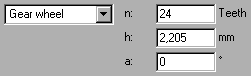
You have selected the Shaft tool and drawn an ellipse of diameter 30 mm. Drag the segment by the central point to 40 mm. Select Gear wheel from the pop-up menu. The shaft segment turns into a gear wheel. At the same time, the entry fields for the changeable dimensions of the Gear wheel variation appear.
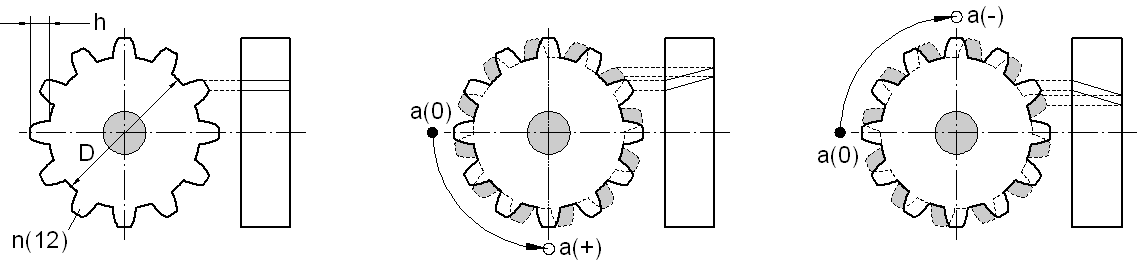
The changeable dimensions of the gear wheel are shown in the first front plane view. In both other drawings, the effect of the angle a is displayed symbolically.
Dimension D specifies the root circle on the gear wheel. This diameter corresponds to that of the shaft segment.
Dimension D specifies the root circle on the gear wheel. This diameter corresponds to that of the shaft segment.
The entry in the entry field next to n specifies the number of teeth at the circumference.
Dimension h specifies the height of the teeth (2 X h + D = outer diameter of the gear wheel).
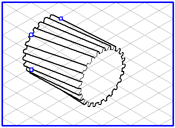
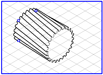
The value at a specifies by how many degrees the rear gear wheel is rotated in relation to the front gear wheel. This corresponds to the angle of inclination for helical gear wheels. If you enter a positive value, the rear gear wheel is rotated counter-clockwise. This gives a helical gear wheel with counter-clockwise twist. If you enter a negative value, the rear gear wheel rotates clockwise. This gives a helical gear wheel with clockwise twist.
The first example shows a helical gear wheel with counter-clockwise twist, the second a helical gear wheel with clockwise twist.
For the Gear wheel shaft segment, all the dimensions are changed in the entry fields. On the drawing, you will only find the handles familiar from the Standard shaft segment for the diameter and the length of the shaft segment.