Preferences for Importing with Arbortext IsoDraw CADprocess
Arbortext IsoDraw CADprocess supports additional options, which are provided specifically for importing 3D IGES files.
When these options are selected, all the assemblies defaulted by the generating CAD system are detected when IGES files are imported. Arbortext IsoDraw CADprocess also creates object info for each of these assemblies. A hotspot can also be generated if required.
These additional functions over and above those offered by Arbortext IsoDraw CADprocess mean that a different preferences page is displayed for selecting import preferences.
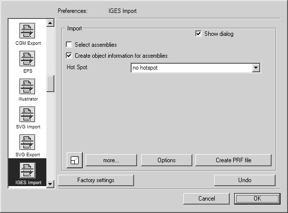
Choose > , then click the IGES Import symbol. The following preferences panel appears for import:
You can set the following preferences for the import process:
Select Assemblies
If you select this option, the Selection of Structures dialog box appears when the file is opened. You can use this to select, which assemblies are to be imported. If you do not select this option, all assemblies in the file will be imported.
Create Object Information for Assemblies
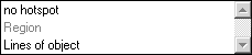
The pop-up menu allows you to select one of the two setting options.
If you select no hotspot, object info is created for each assembly. The name in each case corresponds to the designation assigned in the CAD system for the particular assembly. If you select Lines of object, a hotspot will be generated in addition to the object info. This allows you to trigger an action later by simply clicking the object.
If you do not select the option, the name Group will appear in the object window for each assembly once import has been completed.
Scale
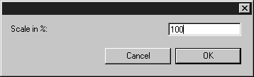
The bottom left corner of the dialog box contains the Scaling button, which you will already be familiar with from the export command. Clicking this button opens the Scaling dialog. You can use it to enlarge or reduce the drawing during the importing stage.
Clicking OK confirms your entry, clicking Cancel aborts the operation.
More
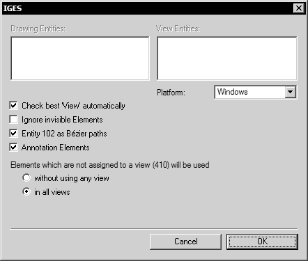
Clicking the more box opens the following dialog box:
Check Best 'View' Automatically
If several view elements are listed in the drawing to be imported, the best view elements will be selected automatically. You can also select additional view elements, if you want to import these.
Ignore Invisible Elements
Some IGES files contain elements, which are marked as invisible, but still should be used for conversion. With this setting you can define if these elements should be used or not.
Entity 102 as Bézier Paths
If the Entity 102 as Bézier paths box has been selected, this IGES element type will be converted to a Bézier path. Otherwise, single elements are generated, which are not joined.
Annotation Elements
A drawing can contain what are known as annotations. These may take the form of texts in the text field, for example. The annotations will be imported if the relevant check box is selected.
Elements That Are Not Assigned to a View (410) Will Be Used
The two buttons below this allow you to control the use of elements that are not assigned to any specific view entity.
As a rule (and as per IGES definition), the description of an element contains information on the views (Views 410) in which it is to be used. In the absence of any special views, there will naturally be no such information, though this situation has been allowed for.
Problems may occur from time to time if several views have been defined. In cases where elements have not been assigned to any view, they are to be used in every view in accordance with the IGES definition. This means that all elements concerned have to be copied into every view. If large files are involved, this procedure can lead to storage problems. In the case of a 3D file with several cross-sections, which have all been defined as views, for example, this can take up several MB of memory space. This is obviously undesirable in most cases. You should therefore select which of the variants suits you best.
You should note, however, that the definition of a view generally incorporates a transformation that changes the existing elements. If they are used outside the view, they may not appear at the correct position in the drawing.
Platform
You can set the platform for the import process. Your selection depends on which platform the original files were generated with.
Clicking OK confirms your entry, clicking Cancel aborts the operation.
Options
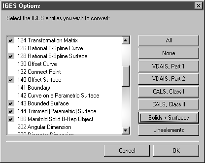
The following dialog box appears if you click Options:
When making imports into Arbortext IsoDraw CADprocess, only surface elements are generally required for converting 3D data into a Technical Illustration. These surface elements are edited so as to ensure the best possible quality of illustration. They are selected automatically by clicking Solids + Surfaces.
Clicking OK confirms your entry, clicking Cancel aborts the operation.
Create a PRF File
If you select this preference, a text file will be created which shows you how the IGES text font types will be converted. Arbortext IsoDraw interprets these font types and assigns a defined font type in each case.
PRF files allow you when making conversions to first define your specific requirements relating to the conversion process. Important points include optimum font mapping and/or substitution and the setting of various graphics options.