Inserting Callout Elements into the Drawing
1. Select New layer from the pop-up menu of the Layer window.
A new layer, layer 3, appears in the layer window. The red dot in front of the layer indicates that it is active. All the elements that you draw now will be assigned to this layer.
|
|
If you draw the callout elements now, these are separate from the drawing on another layer.
In any work that is carried out later, you should also set up a separate layer for callouts, text, etc. Setting up layers makes working on the drawing itself much easier because you can hide or lock layers.
|
2. Select the example style you set up earlier in the Callouts window.
3. Select the
Callout
tool from the toolbox.
The cursor changes into a drawing

cursor.
4. To establish the starting point of the reference line, click on the contour of a part. Holding down the mouse button, drag the line. Release the mouse button once you have reached the desired orientation and length for the reference line.
The text element and the frame of the callout element appear. 1 should appear as the text for the first item number.
5. Position the other parts in the same manner.
The item number automatically increases for each subsequent callout element.
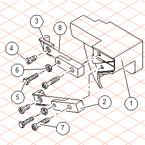
6. The figure below depicts how the positioning could appear.
| To find out how to change and delete callouts, please refer to the Callout tool section of the Arbortext IsoDraw User's Reference. |