Create a Shaft
1. Select the > > menu.
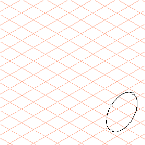
The cursor changes into a drawing

cursor.
The Edit shaft dialog box also appears. It is still not possible to enter any settings.
2. Drag an ellipse with a diameter of 30 mm up and to the right.
| The orientation and size of the ellipse for the starting segment cannot be changed at a later point in time. |
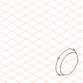
3. Now enter 5 next to Length” in the dialog box and 35 next to Diameter.
The chamfer at the end of the shaft is finished.
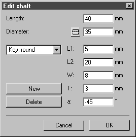
4. Click the New button.
5. Select Key, round from the pop-up menu for design options.
The relevant panels for entering dimensions appear in the dialog box.
Enter the dimensions as follows:
◦ Length40
◦ Diameter35
◦ L15
◦ L220
◦ W8
◦ T3
◦ a-45
The new segment now appears in the entered dimensions.
6. Click New and then enter 50 next to Diameter.
7. Click New again and then enter 15 next to Length, the Diameter remains at 50.
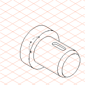
Click New again for the next segment and then enter 20 next to Diameter.
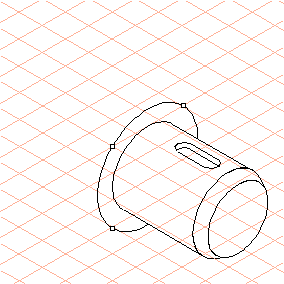
| As the ellipse is hidden behind the previously generated segment, only the dragging points are visible. |
The figure shows part of the ellipse for illustration purposes.
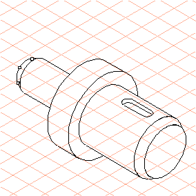
8. Click New and then enter 35 next to Length, the Diameter remains at 20.
Click New again and then enter 5 next to Length and 15 next to Diameter.
This creates the last segment, the chamfer on the rear stump shaft of the shaft drawing.
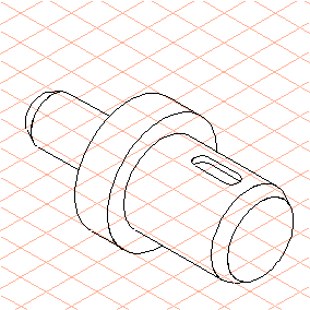
Click OK.
9. The shaft drawing is finished.
The edges of the body are automatically drawn with the thick/thin technique, thus ensuring the correct assignment of outer and inner edges.