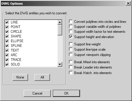
DWG Options
The following dialog box appears if you click the Options button on the DWG Import preferences panel or in the DWG import dialog box.
The list shows all DWG element types that Arbortext IsoDraw can convert. Element types with a check mark will be imported; those without a check mark will not be imported. Clicking an element type shows or clears the check mark.
| Because of the small number of element types in DWG, dimensions cannot be removed from the drawing quite as cleanly as with IGES. Many programs do not write dimensions into the DWG file as a dimension type, but as a series of lines and texts. |
Clicking OK confirms your entry. If you click Cancel, all elements are imported.
Select the DWG entities you wish to convert
The following list shows how these elements can be converted.
| Arbortext IsoDraw is able to process all the major geometric elements of DWG files. However, shapes, attributes, and extensions (e.g., AME) are ignored. |
DWG element | is converted to |
LINE | Line |
POINT | Line (only when extruded) |
CIRCLE | Ellipse |
SHAPE | No conversion |
ELLIPSE | Ellipse |
SPLINE | Bézier path |
TEXT | Text |
ARC | Ellipse |
TRACE | Polygon |
SOLID | Polygon |
INSERT | Group |
ATTDEF | Text |
ATTRIB | Text |
POLYLINE | Ellipses and lines or Bézier path or surface |
POLYFACE MESH | Surface |
FACE 3D | Polygon or surface |
DIMENSION | Group |
RAY | Line |
XLINE | Line |
MTEXT | Text |
LEADER | Line |
MLINE | No conversion |
LWLINE | Ellipses and lines or Bézier path |
PROXY | LWLINE or HATCH |
HATCH | If the Break Hatch into elements check box is: Selected – Hatch elements are converted into basic elements according to the internal pattern. Cleared – Hatch elements are converted into closed, filled Bézier paths. |
VIEWPORT | Viewport (multiple for same elements) |
TOLERANCE | Group of elements, mostly text elements within a border, “Gdt” font must be installed for symbols. |
SURFACE | Surface (derived using AutoDesk® SubDMesh surface generator) |
BODY | Surfaces (derived using AutoDesk RealDWG BREP tesselator) |
SOLID3D | Surfaces (derived using AutoDesk SubDMesh surface generator) |
POLYGON MESH | Surface (derived using AutoDesk SubDMesh surface generator) |
REGION | Surfaces (derived using AutoDesk SubDMesh surface generator) |
HELIX | 3D Bézier path |
TABLE | A group of basic elements such as text and lines. |
MLEADER | Lines and MText (MText is converted according to MText import definitions). |
All line styles defined in the DWG file are converted to Arbortext IsoDraw line styles. You can then select these line styles in the usual way using the Styles attribute window.
The individual elements in a DWG file are assigned colors. A new Arbortext IsoDraw pen is created for each color. Following import, you can assign these pens the required line thicknesses. Width information for polylines is also converted to Arbortext IsoDraw pens.
Furthermore, if you create an OptDWG.prf file, you can use it to map each DWG color index to a color indication in the target ISO file. For example, this allows you to convert a white line in AutoCAD into a black line with a certain line width in Arbortext IsoDraw. The single entries are described in the file OptDWG.prf.
Convert polylines into circles and lines
AutoCAD contains 2D polylines made up of arcs and line segments. It is possible when importing files to generate the polylines as unconnected circles and lines. If the box is not checked, the elements concerned are converted into Bézier paths and interlinked.
Support variable width of polylines
A further feature of polylines is that they can have variable line thicknesses in AutoCAD, i.e. one end of a polyline can be wider than the other. If the appropriate box is checked, the polyline is converted into a Bézier path that is filled and the line thicknesses are displayed. In other cases, a constant line thickness is used.
Support width factor for text elements
DWG files generally specify a factor defining the ratio of the text height to the text width. As a result, text elements need to be scaled horizontally, since the width and spacing of PostScript fonts differ from those used in AutoCAD. However, this scaling operation is superfluous due to the fact that the width of PostScript fonts is governed by the font size. If you ignore this factor, the width of the text element will be determined from the width and spacing of the PostScript characters.
Support height and elevation
If this setting is selected, only the top element is imported where several identical elements are located on top of each other. The associated connecting lines are also ignored. This reduces the storage requirement and makes working with the Arbortext IsoDraw file easier.
Support line weight
This setting imports Linetype Lineweight settings in the selected AutoCAD layout as Pen attribute Width settings in the target ISO file. Turn on Preview in Arbortext IsoDraw to view the PenWidth effects of applied AutoCAD Linetype Lineweights.
• Select the Support line weight check box to import AutoCAD Linetype Lineweights as Arbortext IsoDrawPenWidths.
• Clear the Support line weight check box to ignore Linetype Lineweight settings when importing an AutoCAD layout.
Support line-type scale
This setting imports Linetype scale settings in the selected AutoCAD layout as Pen and line Style attribute settings in the target ISO file.
• Select the Support line-type scale check box to import AutoCAD Linetype scale settings as Arbortext IsoDrawPen and line Style attribute settings.
• Clear the Support line-type scale check box to ignore Linetype scale settings when importing an AutoCAD layout.
Support viewports clipping
This setting imports each viewport in the selected AutoCAD layout as a separate viewport-shaped mask in the target ISO file. When a viewport mask is applied in the target ISO file, only elements and portions of elements inside the mask are visible. Elements and portions of elements outside the mask are clipped and invisible. (See Mask.)
• Select the Support viewports clipping check box to import AutoCAD layout viewports as viewport-shaped masks, and then clip elements outside the viewport masks in the target ISO file.
• Clear the Support viewports clipping check box to ignore layout viewports. No viewport masks are created in the target ISO file.
| When Support viewports clipping is selected, a mask is applied to imported objects in the target ISO file. This moves all masked objects from their original layer(s) into the masking object’s layer. In the Objects window, the masked objects are below the masking object in the objects tree. |
Break Mtext into elements
This setting imports each text line in a multi-line AutoCAD MText entity as a single Arbortext IsoDraw Text element. For each multi-line MText entity in the selected layout, the vertical spacing between the multiple Text elements in the target ISO file matches the vertical line spacing (or “leading”) in the source MText.
• Select the Break Mtext into elements check box to break text lines in multi-line MText entities into separate Text elements with the same vertical line spacing in the target ISO file. (Selecting this option can improve the appearance of imported multi-line text in the target ISO file.)
• Clear the Break Mtext into elements check box to import each multi-line MText entity as a single, multi-line Text element with possibly closer line spacing than the line spacing in the source MText.
Break Leader into elements
This setting imports AutoCAD Leader entities as Arbortext IsoDraw Line elements with line end shapes that match the imported AutoCAD Leader line end shapes.
• Select the Break Leader into elements check box to import Leaders as Line elements with ends that match the Leader line ends in AutoCAD. Line elements imported from Leaders can, for example, have square, triangle, or diamond-shaped line ends. These shapes are in addition to the arrowhead and circle line ends you can select under Options for ends in the Linestyle dialog box. (See Edit Style.)
• Clear the Break Leader into elements check box to import all Leaders as Line elements with arrowhead line ends only.
Break Hatch into elements
This setting imports AutoCAD Hatch entities as patterns of geometric Arbortext IsoDraw elements, such as cross-hatched Line elements or a tiling of Rectangle elements.
• Select the Break Hatch into elements check box to import AutoCAD Hatch entities as geometric Arbortext IsoDraw element patterns.
• Clear the Break Hatch into elements check box to ignore Hatch entities.