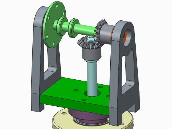
Example: Creating a Weld Notch
1. In an assembly, click
Applications >
 Welding
. The
Welding tab opens.
2. Click
 Weld Wizard
. The
Weld Definition dialog box opens.
3. To create only a notch, under Feature, select the Notch check box, and clear the Edge prep and Weld check boxes.
4. To define the notch shape and size:
a. Under
Notch Feature, select

.
b. Type a value in the Width, Height, Radius boxes.
c. Click OK. The ASSEMBLY WELD NOTCH and the WLD NOTCH TRAJ menus open
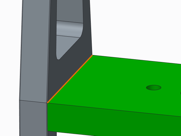
5. To define the notch trajectory (direction for removal of material):
a. Under WLD NOTCH TRAJ, select Select Trajectory. The CHAIN menu opens.
b. Select One By One and Select.
c. In the graphics window, select an edge or a datum curve.
d. Select Done. The Intersected Components dialog box opens.
6. To define the components with which the notch will intersect, in the graphics window, select the components, and click OK.
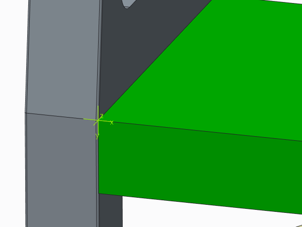
7. To orient the notch:
a. In the ASSEMBLY WELD NOTCH dialog box, select Orient Section, and click Define. The NEXT PREV menu opens.
b. To use a coordinate system to orient the notch, select Coord Sys. The GET COORD S menu opens.
c. Select a coordinate system. The x-axis and y-axis define the cross section of the notch, and the z-axis defines the notch direction.
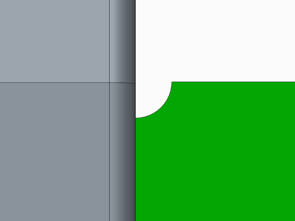
d. Select Done. The notch is created.
8. In the Weld Definition dialog box, click OK.