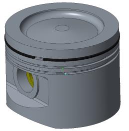
Piston Assembly
Creo retains a model in temporary memory until the model is erased, or until the application is closed.
1. With no model open, on the
Home tab, click
 Erase Not Displayed
 in the
Data group. The
Erase Not Displayed dialog box opens.
2. Click OK.
3. In
Creo Parametric, set the
working directory to
<downloaded files location> > Exercise 3.
4. On the
Home tab, click
 New
New. The
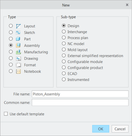
New dialog box opens.
a. Under Type click Assembly.
b. In the Name box, type piston_assembly.
c. Clear the Use default template check box.
d. Click OK. The New File Options dialog box opens.
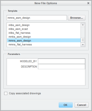
5. In the New File Options dialog box:
a. Under Template, select mmns_asm_design.
b. Click OK.
6. On the
Model tab, click
 Assemble
 from the
Component group. The
Open dialog box opens.
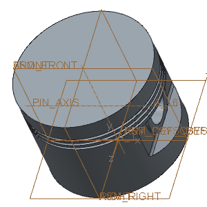
7. Select piston.prt and click Open. The part opens in the graphics window and the Component Placement tab opens.
8. Right-click in the graphics window and click Default Constraint.
9. On the
Component Placement tab, click

.
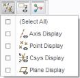
10. On the in-graphics toolbar, click

Datum Display Filters and clear the
(Select All) check box to turn off the display of datum features.
11. In the Model Tree, click

Settings and then click

Tree Filters. The
Model Tree Items dialog box opens.
12. Click Features and click OK.
13. On the
Model tab, click
Assemble from the
Component group. The
Open dialog box opens.
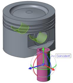
14. Select piston_pin.prt and click Open. The part opens in the graphics window and the Component Placement tab opens.
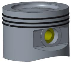
The piston pin requires two assembly constraints. The first is a coincident constraint to align the pin with the hole. The second is a coincident constraint to position the pin in the hole.
15. Set the first constraint to align the pin with the hole.
a. Select the outer cylindrical surface of the PISTON_PIN.PRT.
b. Select the side of the hole surface on the PISTON.PRT.
16. Set the second constraint to position the pin in the hole.
a. In the Model Tree expand PISTON.PRT and PISTON_PIN.PRT.
b. Right-click in the graphics window and click New Constraint.
c. In the Model Tree, select the datum plane RIGHT under PISTON.PRT and datum plane TOP under PISTON_PIN.PRT.
d. On the
Component Placement tab, click the arrow next to
 Distance
, and click
 Coincident
.
e. Click
.
17. On the
Model tab, click
Assemble from the
Component group. The
Open dialog box opens.
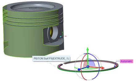
18. Select ring_top.prt and click Open. The part opens in the graphics window, and the Component Placement tab opens.
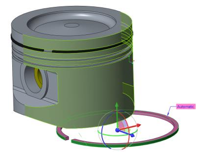
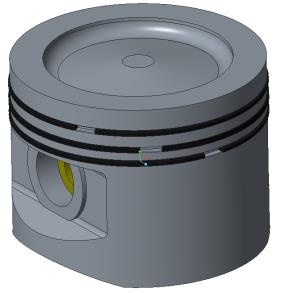
The piston ring requires three assembly constraints. The first is a coincident constraint to concentrically align the ring with the cylinder. The second is a coincident constraint to place the ring onto the surface of the groove. The third is a constraint to rotate the ring to ensure the ring gaps do not align.
19. Set the first constraint to concentrically align the ring with the cylinder.
a. Select the outer cylindrical surface of the RING_TOP.PRT.
b. Select the outer surface of the PISTON.PRT as shown in the following figure.
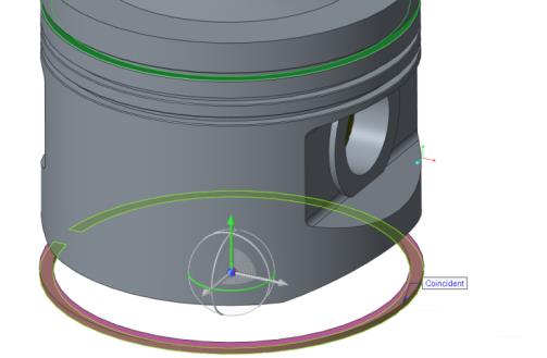
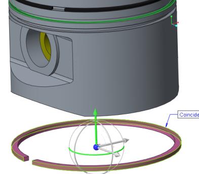
20. Set the second constraint to place the ring onto the surface of the groove.
a. Right-click the graphics window and click New Constraint.
b. Select the bottom planar surface of the RING_TOP.PRT.
c. Select the bottom planar surface in the top groove of the PISTON.PRT.
d. On the
Component Placement tab, click the arrow next to
Distance, and click
Coincident.
21. Set the third constraint to rotate the ring to ensure the ring gaps do not align.
a. Right-click the graphics window and click New Constraint.
b. In the Model Tree, select the datum plane RIGHT under RING_TOP.PRT and datum plane RIGHT under PISTON.PRT.
c. On the
Component Placement tab, change the constraint from
Coincident to
 Angle Offset
.
d. Type 30 for the offset angle value.
e. Click
.
22. On the
Model tab, click
Assemble from the
Component group. The
Open dialog box opens.
23. Select ring_oil.prt and click Open. The part opens in the graphics window and the Component Placement tab opens.
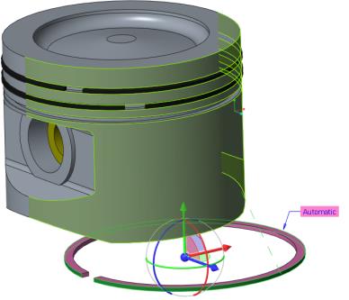
24. Set the first constraint to concentrically align the ring with the cylinder.
a. Select the outer cylindrical surface of the RING_OIL.PRT.
b. Select the outer cylindrical surface of the PISTON.PRT, as shown in the following figure.
25. Set the second constraint to place the ring onto the surface of the groove.
a. Select the bottom planar surface of the RING_OIL.PRT.
b. Select the top planar surface on the middle groove of the PISTON.PRT, as shown in the following figure.
c. On the
Component Placement tab, click the arrow next to
Distance, and click
Coincident.
26. Set the third constraint to rotate the ring to ensure the ring gaps do not align.
a. Right-click the graphics window and click New Constraint.
b. In the Model Tree, select datum plane RIGHT under RING_OIL.PRT and datum plane RIGHT under PISTON.PRT.
c. On the
Component Placement tab, change the constraint from
Coincident to
Angle Offset.
d. Type 60 for the offset angle value.
27. Click
.
28. On the
Model tab, click
Assemble from the
Component group. The
Open dialog box opens.
29. Select ring_bottom.prt and click Open. The part opens in the graphics window and the Component Placement tab opens.
30. Set the first constraint to concentrically align the ring with the cylinder.
a. Select the outer cylindrical surface of the RING_BOTTOM.PRT.
b. Select the outer cylindrical surface of the PISTON.PRT.
31. Set the second constraint to place the ring onto the surface of the groove.
a. Right-click the graphics window and click New Constraint.
b. Select the bottom planar surface of the RING_BOTTOM.PRT.
c. Select the top planar surface on the bottom groove of the PISTON.PRT, as shown in the following figure.
d. On the
Component Placement tab, click the arrow next to
Distance, and click
Coincident.
32. Set the third constraint to rotate the ring to ensure the ring gaps do not align.
a. Right-click the graphics window and click New Constraint.
b. On the Model Tree, select datum plane RIGHT under RING_BOTTOM.PRT and datum plane RIGHT under PISTON.PRT.
c. In the
Component Placement tab, change the constraint from
Coincident to
Angle Offset.
d. Type 90 for the offset angle value.
e. Click
.
All three rings are now assembled.
33. Click an empty place in the graphics window to deselect all items.
34. In the
Model tab, click
 Axis
Axis from the
Datum group. The
Datum Axis dialog box opens.
a. Hold down the CTRL key, and select datum planes ASM_RIGHT and ASM_FRONT on the Model Tree.
b. Click the Properties tab and type piston in the Name box.
c. Click OK.
35. To hide the display of the reference datum planes by using layers, do the following:
a. On the
View tab, click
 Layers
 from the
Visibility group. The Layer Tree opens.
b. Hold down the CTRL key and select the seven layers shown in the following figure.
c. Right-click on the Layer Tree and click Hide.
36. On the
View tab click
 Save Status
 from the
Visibility group to save the layer display settings.
37. On the Quick Access toolbar, click
 Save
Save.
38. On the Quick Access toolbar, click
 Close
Close.