Working with Patterns
In this exercise, you recognize a pattern, make changes to the model, and propagate the changes to pattern members. This exercise includes the following tasks:
Recognize a pattern
In this task, you will select a ring-shaped surface, and use it to recognize a pattern.
1. In Creo Parametric, set the working directory to <downloaded files location>, and open linkage_pat.prt.
2. To disable all datum display filters, click
 Datum Display Filters
 on the in-graphics toolbar, and clear all the check boxes.
3. To set the model view, click
 Saved Orientations
 on the in-graphics toolbar, and select
VIEW 1.
4. Click the Flexible Modeling tab.
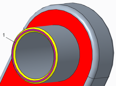
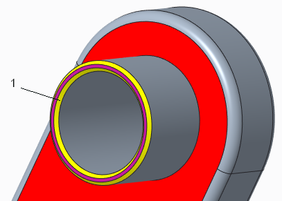
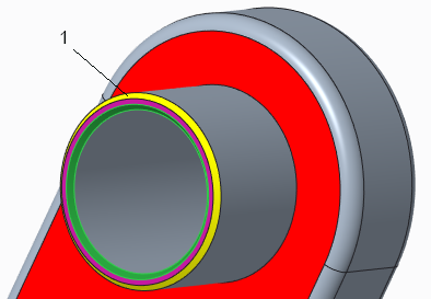
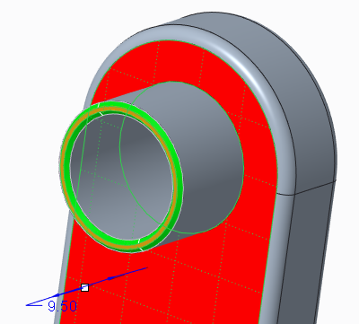
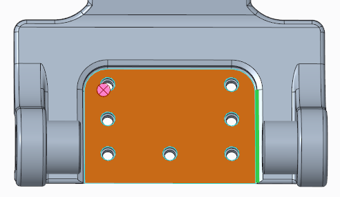
5. Zoom in and select the purple ring-shaped surface.
1. Purple ring-shaped surface
6. To select the entire boss of which the selected surface is a part, along with smaller surfaces that intersect it, in the
Shape Surface Selection group, click
 Bosses
.
7. To identify geometry that is identical to or similar to the selected geometry, in the
Recognition group, select
 Pattern
. The
Pattern Recognition tab opens. Notice that two instances were found.
8. Click

. The Pattern Recognition feature appears in the Model Tree.
Recognize chamfers, and propagate the chamfers to other pattern members
In this task, you will recognize chamfers, and propagate the recognized chamfers to the previously recognized pattern.
1. Click
Saved Orientations on the in-graphics toolbar, and select
VIEW 1.
2. Select the yellow chamfered surface that is located inside the purple surface.
1. Inner yellow surfaces
3. To identify connected chamfer surfaces of the same size, type, and convexity, on the mini toolbar, click
 Rounds/Chamfers
. The entire inner yellow chamfered surface is selected.
4. Hold down the CTRL key while you select the yellow chamfered surface that is outside of the purple surface.
5. To identify connected chamfer surfaces, on the mini toolbar, click
Rounds/Chamfers. The entire inner yellow chamfered surface is selected.
6. To identify chamfer-like geometry, in the
Recognition group, select
 Rounds/Chamfers
 >
 Recognize Chamfers
. The
Recognize Chamfers dialog box opens. The inner and outer yellow surfaces are listed in the
Recognize and tag as chamfer collector.
7. To propagate the recognized chamfers to the second pattern member:
a. In the Recognize Chamfers dialog box, click the Options tab.
b. Click the Pattern/Symmetry/Mirror Feature collector to activate it.
c. To select a pattern to which to propagate the recognized chamfers, in the Model Tree, select Pattern Recognition 1.
d. Click OK. The Propagation of Recognize Chamfers 2 feature appears in the Model Tree.
Move geometry, and propagate the move to other pattern members
In this task, you move a surface in one pattern member, and then propagate the move to the other pattern member.
1. Click
Saved Orientations on the in-graphics toolbar, and select
VIEW 1.
2. In the
Transform group, click the arrow under
 Move
Move, and select
 Move by Dimension
. The
Move tab opens.
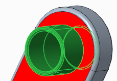
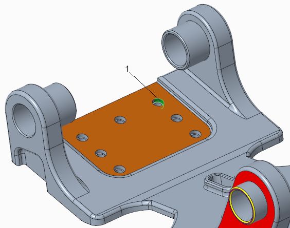
3. Select the purple surface.
1. Purple surface
4. To define references for the dimension:
a. On the Dimensions tab, click the References tab to activate it.
b. Select the purple surface again.
c. Hold down the CTRL key while you select the red surface. A dimension appears in the graphics window.
5. Edit the dimension value to 6. Notice that only the boss you edited changes.
6. To propagate the Move to other pattern members, click the Options tab, click the Pattern/Symmetry/Mirror feature collector to activate it, and then in the Model Tree, select Pattern Recognition 1. The move is propagated to the second pattern member.
7. Click
. The Propagation of Move 3 feature appears in the Model Tree.
Recognize and edit a pattern
In this task, you will select one of four holes, use the hole to recognize a pattern, and edit the pattern.
1. Click
Saved Orientations on the in-graphics toolbar, and select
VIEW 2.
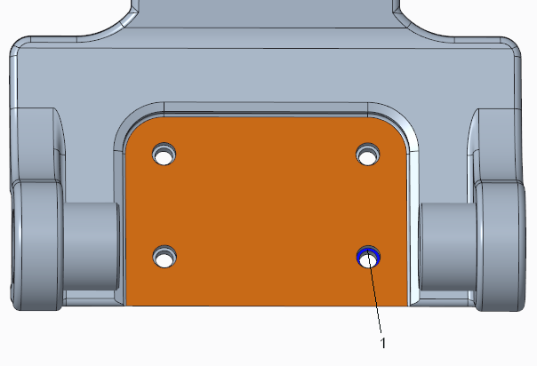
2. Select the blue planar surface inside the hole on the bottom right.
1. Blue planar surface
3. To select the entire cut of which the selected surface is a part, along with smaller surfaces that intersect it, click
 Cuts
Cuts. The surfaces of the hole are selected.
4. To identify geometry that is identical to or similar to the selected geometry, in the
Recognition group, select
Pattern. The
Pattern Recognition tab opens. Notice that all four hole instances were found and are represented by

black dots.
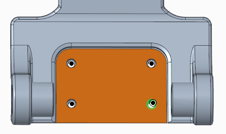
5. To edit the pattern:
a. Click the Options tab, and select the Allow edit check box.
b. For the first direction, change Instances to 3, and Spacing to 17.1.
c. For the second direction, change Instances to 3, and Spacing to 10.
d. In the graphics window, in the middle of the pattern, deselect the top middle pattern instance, and the instance below it. The dots for the deselected pattern instances turn

white.
6. Click
. The Pattern Recognition 2 feature appears in the Model Tree.
Restrict the instances that are recognized in a pattern
In this task, you will control the scope of the pattern recognition to only include a defined subset of pattern members.
1. Click
Saved Orientations on the in-graphics toolbar, and select
VIEW 2.
2. Select the planar surface inside the hole on the bottom right.
3. Click
Cuts. The surfaces of the hole are selected.
4. To identify geometry that is identical to or similar to the selected geometry, in the
Recognition group, select
Pattern. The
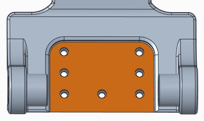
Pattern Recognition tab opens. The recognized pattern instances are represented by
black dots.
5. Click the Options tab, and select the Restrict pattern recognition check box. Options become active.
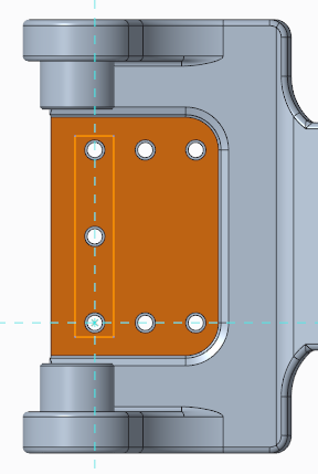
6. Select the Sketch option, and then click Define. The Sketch dialog box opens.
a. To define the sketch plane, select the orange surface.
b. To define a sketch reference, select an additional edge.
c. To close the dialog box, click Sketch. The Sketch tab opens.
7. To orient the sketch plane parallel to the screen, on the in-graphics toolbar, click
 Sketch View
.
8. To create a sketch to define the pattern members to recognize, on the
Sketch tab, click
 Corner Rectangle
, and then draw a rectangle around only the pattern members to recognize.
9. Click
OK to complete the sketch.
10. Click
to complete the feature. A pattern recognition feature that includes only the recognized pattern members is created. Pattern Recognition 3 feature appears in the Model Tree.
Observe how changes are propagated to only recognized pattern instances
Edit one pattern member, and observe how changes are propagated to only the instances that you included in the Recognition feature.
1. Click
Saved Orientations on the in-graphics toolbar, and select
VIEW 3.
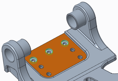
2. Select the cylindrical surface of the pattern member in the upper corner.
3. In the
Transform group, click
 Modify Analytic
.
4. Change the Radius value from 2 to 3.
5. Click the Options tab, and then click the Pattern/Symmetry/Mirror feature collector to activate it.
6. To select the pattern to which to propagate the radius change, in the Model Tree, select the Pattern Recognition 3 feature. Notice that only the three recognized pattern members are updated.
7. Click
to complete the feature.
8. Save and close the model.