About Flat Patterns
Use the Flat Pattern tool to automatically create a flattened version of a sheet metal part and prepare the model for manufacture. The Flat Pattern feature remains the last feature in the Model Tree and maintains the flat model view. The flat pattern is suppressed when you add or redefine features in a design. It is automatically resumed after the features have been added. A model can have only one flat pattern. Create the Flat Pattern feature as you would using the Unbend tool.
After you create a Flat Pattern feature, use the Bounding Box Dimensions command on the View tab to toggle the display of the length and width dimensions of the unbent sheet metal part. The dimensions are associated with the SMT_FLAT_PATTERN_LENGTH and SMT_FLAT_PATTERN_WIDTH parameters.
When you create a Flat Pattern feature, you must define a fixed surface or edge. You can save time and maintain consistency by setting at part-level a fixed geometry reference for all Unbend, Bend Back, and Flat Pattern operations in the Fixed Geometry dialog box.
Keep in mind the following points when creating a Flat Pattern feature:
• You cannot manually select bent geometry.
• You cannot create a flat pattern for a part with more than one distinct pieces of unattached geometry.
• When surfaces are detected that require the creation of deformation areas, specify treatment of the areas as you would using the Unbend tool.
• You can project cuts added to forms to the flat pattern.
• Use the Flat Pattern Preview tool to open a window that displays the model in an unbent condition, when there is no Flat Pattern feature in the model.
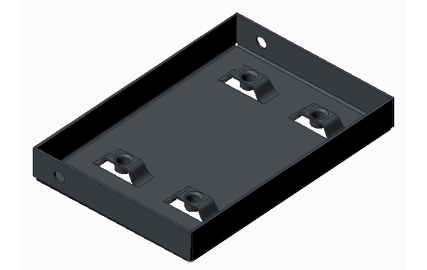
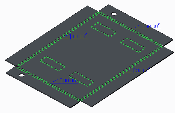
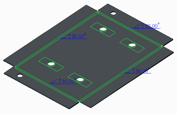
The following figures show options for creating flat patterns
• Sheet metal part
• Flat pattern with bend notes
• Flat pattern with bend notes and projected cuts