Starting Creo Parametric and setting the environment
1. Start Creo Parametric.
Although not required, setting up a black background makes the dimensions easier to see and read.
2. Click File > Options. The Creo Parametric Options dialog box opens.
3. Click System Appearance. Options for changing system colors appear.
4. In the System Colors select Dark and then click OK.
Since you are doing a tolerance analysis, turn on the tolerance display.
5. ClickFile > Options. The Creo Parametric Options dialog box opens..
6. Click Entity Display. Options for changing the appearance of entities appear
7. Select the Show dimension tolerances check box and then click OK.
Two separate analyses will be conducted. The objective of the first analysis is to determine whether it is possible to assemble the PCB into the assembly. The objective of the second analysis is to determine if the PLUG will interfere with opening in the sheetmetal PAN.
The current assembly process specifies that the bottom screws are to be installed and tightened first. Next, the plug is snapped into holes in the PCB. Then the PCB assembly is placed into the assembly and the top screws inserted and tightened. There should be a minimal gap between the plug and the pan, but an interference condition could prevent the ability to insert the screws into the PCB.
Analysis 1: PCB Subassembly into PAN
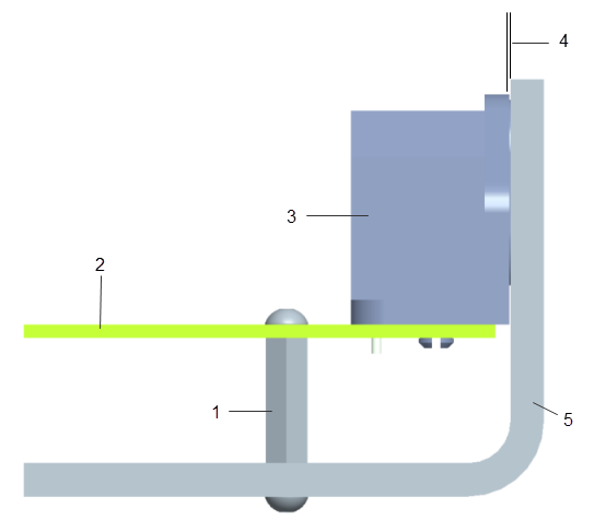
1. Standoff
2. PCB
3. Plug
4. Clearance
5. Pan