![Next Page [Next Page]](../Nav_NextD.png)
![Integration Kit What's New [Integration Kit What's New]](../Nav02_WhatsNew.png)
![Next Page [Next Page]](../Nav_NextD.png) ![Integration Kit What's New [Integration Kit What's New]](../Nav02_WhatsNew.png) |
Generic user interfaces in Creo Elements/Direct Modeling can be built with the User Interface Construction Toolkit.
The base for all generic user interfaces in Creo Elements/Direct Modeling is a dialog shell. This dialog shell provides an empty client area (Area) which can be filled with more user interface elements.
Areas don't have a
size and can contain additional areas or grid areas as children.
Areas can't contain user interface controls like push or toggle
buttons. Just grid areas (see below) can contain such controls as
children.
Areas are useful to create the basic layout of your user interface. Since
you can hide and show single areas you can build up user interfaces which
resize automatically to accommodate all visible user interface portions.
Areas can be appended from left to right to a parent area. Newlines
can be added to continue adding areas in the next row until you finished
your basic layout of your user interface.
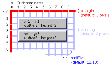
Into each area you can put a Grid Area which serves as basis for the real user interface controls like push buttons, text controls and so on. You have to specify a size for a grid area. This size is always measured in parent units. That means if the parent of a grid area is a normal area, the units will be pixels. If the parent of a grid area is another grid area, the size of the child grid area is measured in grid units of the parent.
The default grid units (cellSize) of a grid area are 10x10 pixels.
The following picture illustrates the meaning of cellSize,
margin and spacing as parameters for grid areas. In addition
to that it shows how single controls will be placed into grid areas.

Obviously, the margin of an area reduces the usable size where controls can
be placed by the margin's value in both x- and y-direction. The same can be
stated for the spacing parameter. A spacing not equal to zero shrinks the
real size of the control by this value in both directions.
Click here for an example.
The UICT documentation shows you in detail, what kind of controls can be created with the User Interface Construction Toolkit and what kind of properties each single control supports.
Control Actions can always be specified in two ways:
![Next Page [Next Page]](../Nav_NextD.png) ![Integration Kit What's New [Integration Kit What's New]](../Nav02_WhatsNew.png) |
| © 2024 Parametric
Technology GmbH (a subsidiary of PTC Inc.), All Rights Reserved |