Example Design Information Features
Overview
Loading this file makes available several examples of simple Design
Information features. Included are the following:
- Example Paint feature
- Example Simple tapped hole feature
- Example more complex tapped hole feature
- Validate feature command
Activation
Enter into command line
(load "example_features")
Or add this line to your customization file.
This will add a new button in toolbox for validation of feature and add
the example features to design information module.
Description
All example features are available when the
Design Information module is active. To construct any one of the examples,
use the create button in the design information menu. A browser will be
displayed showing all available design information features including the
ones just loaded. Once contructed, any design information can be modified or
copied using the design information modify and copy commands. In addition,
design information features can be used in commands which allow selection of
features (i.e. move faces, align, offset,...).
Usage
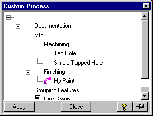
- Paint feature (My Paint)
-
The paint feature allows the attachment of color and paint type to be
associated with a collection of faces. This paint feature is a simple
example of a non-geometric feature.
- Select paint feature from Design Infos browser.
- Identify the faces to attach the paint feature.
- Pick the color the paint.
- Enter the type of paint.
A Design Information feature will be constructed and the faces
associated with the feature will be colored as specified.
- Simple Tapped-Hole
-
The simple tapped-hole feature is an example of a geometric feature with
advisor feedback. This design information will construct the tapped hole
and associate the design intent with it.
- Pick the center point of the tapped hole.
- Pick a diameter from the possible range.
- Select a depth.
In addition to the above parameters being attached to the faces
constructed by this design information, a URL is attached which
specifies how this tapped hole must be constructed. In this simple
example, a link to the Spiralock Corporation is provided as an example.
To access this link, create a report of the design information, and pick
on the specification link. Note: If a depth is specified that is
more than 2 times greater than the diameter, an adivsor warning is
displayed. If a depth is too shallow, an error is generated.
- Tapped hole example
-
This is an example of a more complex tapped hole. This geometric feature
will produce a more realistic representation of a tapped hole
constructed using a center hole drill that is tapped and then chamfered.
The face colored in white represents the actual thread location.
- Pick the center point.
- Select if inch or metric threads are desired.
- Pick the size from the table.
- Modify the depth as desired.
- Validate Feature command.
-
This utility function is placed in the toolbox. Use this command to
validate a feature that has been marked as invalid when the modify
design information command is unable to do so.
Situation:
Normally, to validate an invalid design information, one must simply use
the modify design information command. However, in some cases, modifying
one geometric design information can cause another to become invalid.
This can cause a cyclic effect. To fix this problem use the supplied
utility function.
- Pick the feature to validate.
The feature then is marked as valid if the verification function is
present and returns true.
© 2024 Parametric
Technology GmbH
(a subsidiary of PTC Inc.), All Rights Reserved |