To Set Connection Report Columns
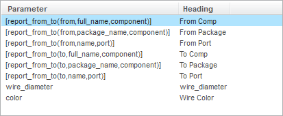
In the Format report dialog box Column tab, define columns to match the figure below.
Add From columns:
1. Click Add <Label> Column. A new line is added to the table.
2. Click [fn(x)]. The Select a function dialog box opens.
3. Select Get ‘from’ component ({from|to},{parameter name}, {both|port|component}.
4. Click OK. A line is added in the table and in the Parameter Format box.
5. Edit the text in the Parameter Format box to [report_from_to(from,full_name,component)]. Type From Comp in the Column Heading box.
6. Add a second From column and edit the Parameter Format to [report_from_to(from,package_name,component)]. Type From Package in the Column Heading box.
7. Add a third From column and edit the Parameter Format to [report_from_to(from,name,port)]. Type From Port in the Column Heading box.
Add To columns:
1. Click Add <Label> Column. A new line is added to the table.
2. Select Get ‘to’ component ({from|to},{parameter name}, {both|port|component}.
3. Click OK. A line is added in the table and in the Parameter Format box.
4. Edit the text in the Parameter Format box to [report_from_to(to,full_name,component)]. Type To Comp in the Column Heading box.
5. Add a second To column and edit the Parameter Format to [report_from_to(to,package_name,component)]. Type To Package in the Column Heading box.
6. Add a third To column and edit the Parameter Format to [report_from_to(to,name,port)]. Type To Port in the Column Heading box.
Add parameter columns:
1. Click Add Parameter Column. The Parameter Selector dialog box opens.
2. Select the parameter wire_diameter and click OK.
3. Type wire_diameter in the Column Heading box.
4. Click Add Parameter Column. The Parameter Selector dialog box opens.
5. Select the parameter color and click OK.
6. Type Wire Color in the Column Heading box.