To Define Fillet Weld Location
You must be on the Fillet Weld tab to perform this procedure.
1. Click the Location tab.
2. Select references to define the weld location:
a. For

both sided symmetrical welding, use the
Weld sets list to select the
Arrow Side and
Other Side so you can select reference sets for each side.
b. Under
Side 1, select references in the graphics window. You can click
Details to open the
Surface Sets or
Chain dialog box to help collect references. The reference type depends on the selected
weld dimension scheme:
▪ D x D (ANSI only)—Select surfaces.
▪ D1 x D2 (ANSI only)—Select surfaces.
▪ a (ISO only)—Select surfaces.
▪ z (ISO only)—Select surfaces.
▪ Angle—Select chains. When defining a solid weld, click the Side 1 Weld Surfaces collector and select surfaces to further define Side 1.
▪ None—Select chains. When defining a solid weld, click the Side 1 Weld Surfaces collector and select surfaces to further define Side 1.
c. Under Side 2, select references in the graphics window:
▪ D x D (ANSI only)—Select surfaces.
▪ D1 x D2 (ANSI only)—Select surfaces.
▪ a (ISO only)—Select surfaces.
▪ z (ISO only)—Select surfaces.
▪ Angle—Select surfaces.
▪ None—Select chains. When defining a solid weld, click the Side 2 Weld Surfaces collector and select surfaces to further define Side 2.
3. To extend a weld trajectory in both directions along adjacent tangent surfaces during weld calculation, select the Allow tangent propagation check box.
4. To create a weld trajectory along the edges formed by the boundary of the area where two contact surfaces overlap, select the Treat side surfaces as contact surfaces check box.
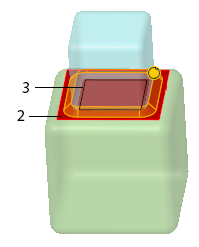
1. Selected surface at the bottom of the blue block
2. Selected surface at the top of the green block
3. Weld trajectory is created along the edges formed by the boundary of the area where the two contact surfaces overlap
5. To edit the start or end of an intermittent weld joint:
a. In the Weld joints table, under Joint, select the joint to edit. The Details button becomes active.
b. Click
Details. The
Joint dialog box opens.
c. In the Joint dialog box, edit the joint start and end:
▪ In the Start list, select an option to set the joint start location:
▪ Select Chain End to start the joint at the end of the chain.
▪ Select Blind to start the joint offset from the chain end, and then type an offset value in the box that appears.
▪ Select To Selected to set the joint by using a reference, and then select a reference in the collector that appears. If you select a coordinate system axis or datum plane, type an offset value in the box that appears.
|  For a reference to be valid, a point, curve end, or vertex must be located on the joint. A surface or a plane must intersect the joint. You can also select a coordinate system axis. |
▪ In the End list, select Chain End, Blind and type a value, or To Selected and select a reference and, if you select a coordinate system axis or datum plane, type an offset value.
▪ To change the start point of the joint to the end point of the next joint, click Next end.
▪ To activate the joint that is listed before the current joint in the Weld joints table, click Previous joint.
▪ To activate the joint that is listed after the current joint in the Weld joints table, click Next joint.
d. Click OK. The Joint dialog box closes.
6. To exclude an intermittent weld joint segment from weld geometry creation, in the Weld joints table under Status, select Excluded from the list in that segment's row.
7. To display a weld symbol for a joint segment or remove symbol display, in the Weld joints table under Attachment, select Yes or No from the list in that segment's row
8. If you selected

on the tab to manually set a lightweight weld trajectory, click the
Lightweight weld trajectory collector, and then select a chain reference in the graphics window.
9. To flip the material side 180°, click Flip material side.