Working with Rounds and Chamfers
In this exercise, you learn to recognize geometry that is round-like or chamfer-like. This enables you to edit the geometry as if it were rounds or chamfers. You can edit the round and chamfer types and values, and remove rounds and chamfers. The procedure for working with chamfers is similar to the procedure for working with rounds.
This exercise includes the following tasks:
Select and edit a chain of rounds or chamfers
In this task, you select and edit a chain of rounds.
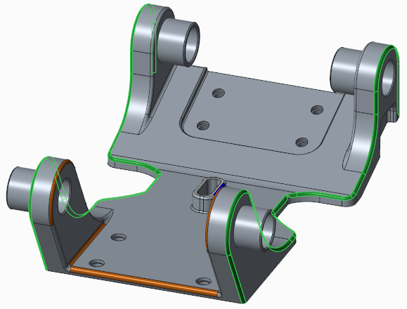
1. In Creo Parametric, set the working directory to <downloaded files location>, and open linkage_rc.prt.
2. To disable all datum display filters, click
 Datum Display Filters
 on the in-graphics toolbar, and clear all the check boxes.
3. To set the model view, click
 Saved Orientations
 on the in-graphics toolbar, and select
VIEW 1.
4. Click the Flexible Modeling tab.
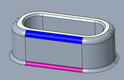
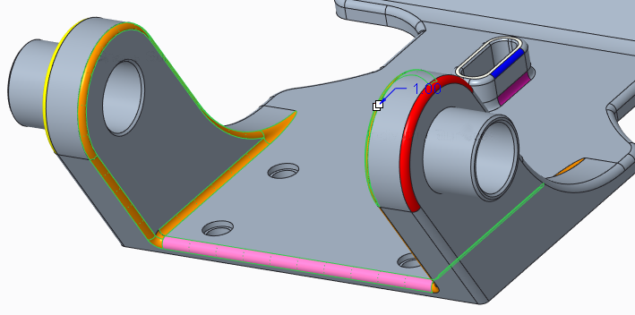
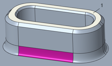
5. In the graphics window, select the pink round.
6. To select the entire chain of rounds, in the
Shape Surface Selection group, click
 Rounds/Chamfers
.
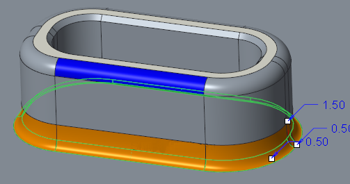
7. To edit the round:
a. In the
Transform group, click
 Edit Round
. The
Edit Round tab opens.
b. To change the round type, click the arrow next to Circular, and select D1 x D2 Conic from the list.
c. Drag the upper drag handle upwards to change the D1 dimension to 1.5.
8. Click

to accept the feature.
Edit multiple rounds—shape surfaces selection
In this task, you use shape surface selection to select rounds.
1. Click
Saved Orientations on the in-graphics toolbar, and select
VIEW 2.
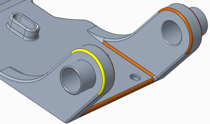
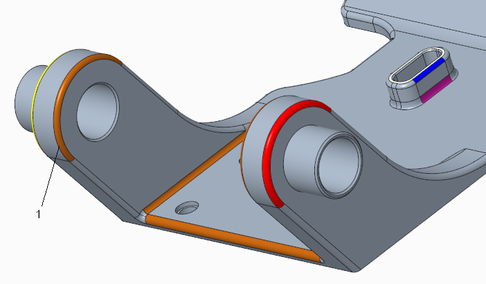
2. In the graphics window, select the yellow round.
3. To select the entire chain of rounds, in the
Shape Surface Selection group, or on the mini toolbar, click
Rounds/Chamfers.
4. To rotate the model, click
Saved Orientations on the in-graphics toolbar, and select
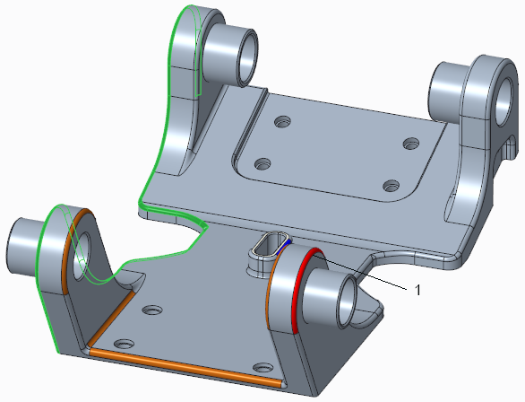
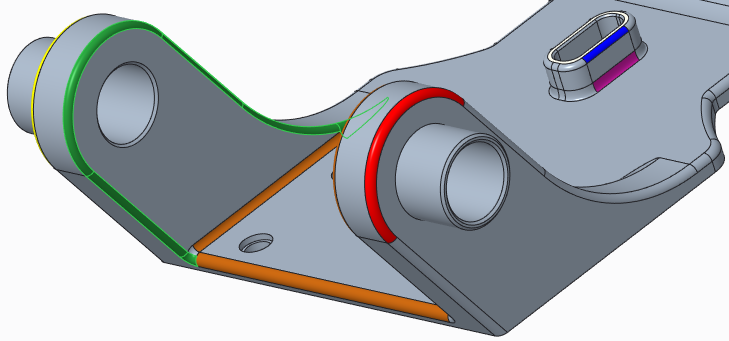
VIEW 3.
1. Red round
5. To add more surfaces to the selection:
a. Press and hold down the CTRL key while you select the red round as a seed surface.
b. In the
Shape Surface Selection group, or on the mini toolbar, click
Rounds/Chamfers. More rounds are added to the selection.
6. To edit the selected rounds:
a. In the
Transform group, click
Edit Round. The
Edit Round tab opens.
b. In the Radius box, change the value from 1.0 to 1.2.
7. Click
to accept the feature.
Select and edit a large number of rounds or chamfers
In this task, you select a large number of rounds to edit.
1. Click
Saved Orientations on the in-graphics toolbar, and select
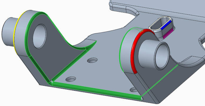
VIEW 4.
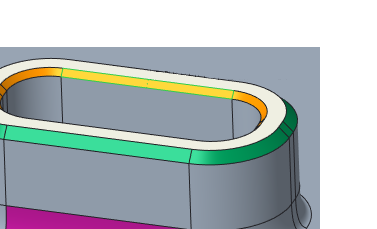
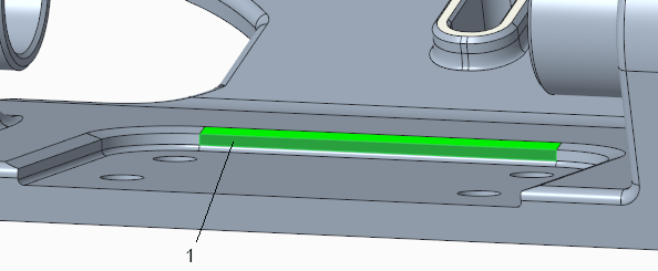
2. Select the orange surface on the left as a seed surface.
1. Orange surface
3. To select the entire chain of rounds, in the
Shape Surface Selection group, click
Rounds/Chamfers.
4. To add more surfaces to the selection:
a. Press and hold down the CTRL key while you select another orange round as a seed surface.
b. Continue holding down the CTRL key while you select the remaining orange surfaces. If you want to turn the model, release the CTRL key, but press it again before you select another surface.
5. To edit the selected rounds:
a. In the
Transform group, click
Edit Round. The
Edit Round tab opens.
Note that one round is colored pink. This indicates that it has a different radius than other rounds in the selection.
b. In the Radius box, change the value from 1.0 to 1.2.
c. Press ENTER. This changes the radius of all the selected rounds.
6. Click
to accept the feature.
Remove rounds or chamfers
In this task, you will remove a round.
1. Click
Saved Orientations on the in-graphics toolbar, and select
VIEW 1.
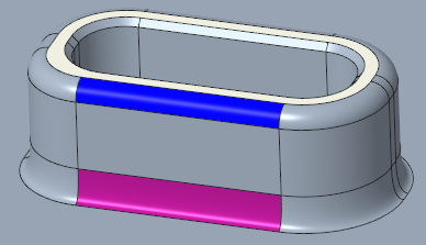
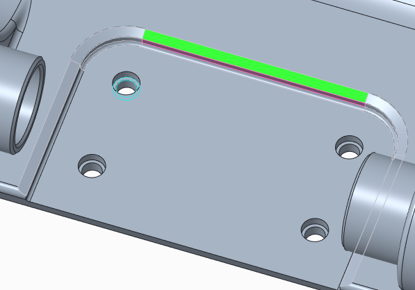
2. Select the blue round surface as the seed surface.
3. To select the entire chain of rounds, in the
Shape Surface Selection group, click
Rounds/Chamfers.
4. In the
Transform group, click
Edit Round. The
Edit Round tab opens.
5. On the Edit Round tab, select the Remove round check box.
6. Click
. The round is removed.
Recognize rounds or chamfers
When you recognize round-like or chamfer-like geometry, you can edit the round or chamfer type and value, and remove the round or chamfer.
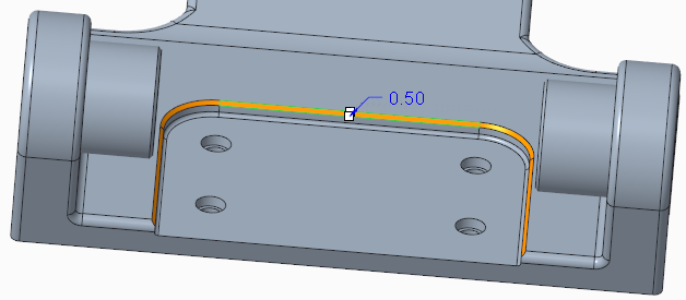
1. To create a chamfer:
a. Click the Model tab.
b. In the
Engineering group, click the arrow next to
 Chamfer
, and click
Edge Chamfer.
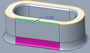
c. On the model, select one of the upper, outer edges.
d. Change the value from 0.04 to 0.5, and press ENTER.
e. Click
to accept the feature. A chamfer is created.
2. To create a Recognize Chamfers feature so the system can recognize the surfaces that you specify as chamfers:
a. Click the Flexible Modeling tab.
b. In the
Recognition group, click
 Rounds/Chamfers
, and select
 Recognize Chamfers
. The
Recognize Chamfers dialog box opens.
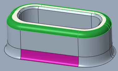
Note that the chamfer you just created is highlighted in green because it has a design intent. The inner chamfer is not highlighted.
1. Inner chamfer
c. Select one of the surfaces of the inner chamfer. In the Attributes area of the Recognize Chamfers dialog box, note the chamfer recognition values.
d. In the Recognize Chamfers dialog box, click OK. A Recognize Chamfers feature appears in the Model Tree.
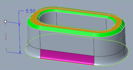
3. To observe the chamfers during a move:
a. In the lower right corner of the Creo window, ensure the selection filter is Regions and Surfaces.
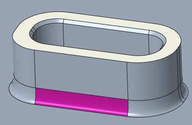
b. On the model, select the top white surface.
1. Top white surface
c. To select the type of move, in the
Transform group, click the arrow under
 Move
Move, and select
 Move by Dimension
. The
Move tab opens.
d. Hold down the CTRL key while you select the top white surface again, and the surface on which the extrusion is located.
e. Change the height dimension value from 5.5 to 3. Notice that the chamfers are kept during the move.
f. Click
to accept the feature.
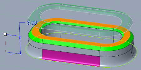
4. To edit chamfers:
a. Click
Saved Orientations on the in-graphics toolbar, and select
VIEW 5.
b. In the
Transform group, select
 Edit Chamfer
. The
Edit Chamfer tab opens.
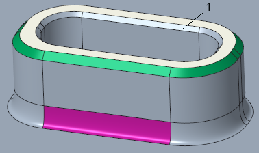
c. Zoom in and select the green middle chamfer surface.
Notice that the entire chamfer is selected.
d. Change the chamfer type from D x D to D1 x D2.
e. Drag the upper handle until the D2 value is 1.5.
f. Click
to accept the feature.
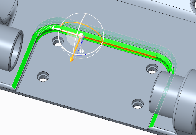
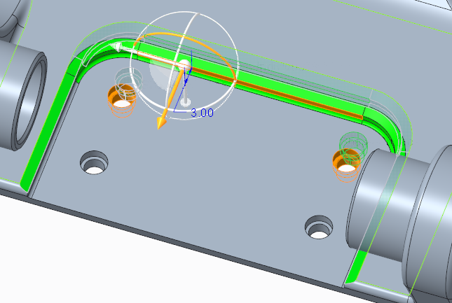
5. Add holes to a move:
a. Select the vertical surface below the chamfer.
1. Vertical surface
b. In the
Transform group, click the arrow under
Move, and select
Move using Dragger. The
Move tab opens.
c. To position the dragger, click the selected surface again.
d. Pull the dragger, and edit the distance value to 3.
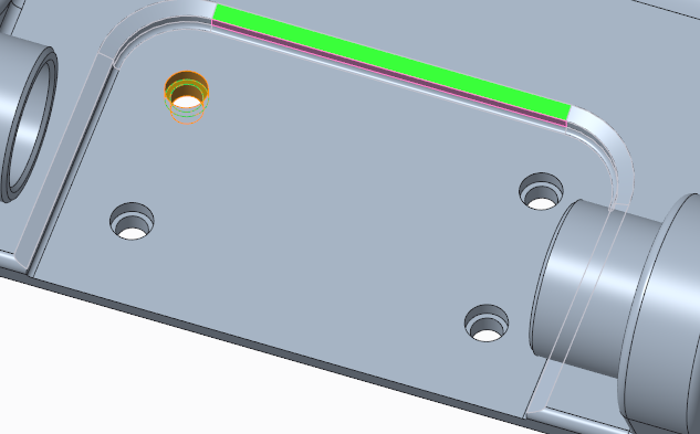
e. To add surfaces to the move, click the References tab, and next to the Move surfaces collector, click Details. The Surface Sets dialog box opens. Do the following:
a. Click Add, and select the planar surface of the top left hole.
b. In the Surface Sets dialog box, select Shape surfaces. The Primary shape options appear.
c. Select Cut. The entire cut of which the selected surface is a part becomes selected.
f. Click Add again, and select the planar surface of the top right hole.
g. Click OK. The Surface Sets dialog box closes. Both holes are now included in the move feature.
6. Click
. The surface and the holes move to the new position.
7. Save and close the model.