Setting App Options
The system application options are defined in the GDTAAppOptions.xml file that is located in the …\Common Files\gdt_home folder in the Creo Parametric installation.
This XML file contains five primary elements: Restricted, AppOptions, AdvisorTest, StandardHoleText, and ApplicationNotes. Note that if you edit the GDTAAppOptions.xml file, you must stop and restart GD&T Advisor for those changes to take effect.
Restricted GCSs
The Restricted element includes an attribute representing each geometric characteristic symbol that can potentially be restricted. Setting the attribute value to "Y" sets the geometric characteristic symbol as restricted, meaning that that symbol will be filtered from the Geometric Characteristic Symbol Selector menu. The selected options are shown on the System Options/Restricted GCS tab of the Application Options dialog window.
Optional Settings
The AppOptions element of the file allows you to define various Option elements for the application. The Option element has the following form:
<Option name="option_name" value="option_value"/>
The following options control the content for various text strings:
• ASME_Multi-surface_Text — For multi-surface features (See
Feature Descriptions) the geometric tolerance annotation includes a note that indicates the number of surfaces that the annotation applies to (e.g., 3 SURFACES, where ' SURFACES' is the value for this option). This option is applicable only to models that reference the ASME tolerancing standards.
• ASME_Pattern_Number_Text — An annotation for a pattern of a feature of size includes an indication of the number of members of the pattern (e.g., 3X, where 'X ' is the value for this option). This option is applicable only to models that reference the ASME tolerancing standards.
• ISO_Multi-surface_Text — For multi-surface features (See
Feature Descriptions) the geometric tolerance annotation includes a note that indicates the number of surfaces that the annotation applies to (e.g., 3x, where 'x' is the value for this option). This option is applicable only to models that reference the ISO tolerancing standards.
• ISO_Pattern_Number_Text — An annotation for a pattern of a feature of size includes an indication of the number of members of the pattern (e.g., 3 x, where ' x ' is the value for this option). This option is applicable only to models that reference the ISO tolerancing standards.
• ISO_Thread_Depth_Text — The string specified for the value of this option defines optional text to be appended to the dimension annotation for thread depth dimensions. This option is applicable only to models that reference the ISO tolerancing standards.
• Draft_Angle_Text — The string specified for the value of this option defines text to be appended to the dimension annotation for draft angle dimensions.
For any text string option, you may specify a null string ("") for the value if you do not want to have any text appended to the annotation. If you do not include an option for one of the text string options in the application options file, the application will use a default string value.
The following options control other aspects of the model:
• PLN_DFS_Attach — Allows you to define one of the following values for how the Set Datum Tag annotation is placed for a planar surface that is set as a datum feature:
◦ In Gtol
◦ On Geometry
• FOS_U_Min — The number specified for the value of this option defines the minimum portion (i.e., degrees) of a cylindrical or conical surface that is required in order to be considered a feature of size. The specified value must be between 160 and 359.
Note that none of these values are displayed in the application options dialog in the GD&T Advisor user interface.
Parameters
The AdvisorTest element includes a number of AdvTestParam elements. Each AdvTestParam element has a name attribute corresponding to the parameter and a value attribute to define the value for the parameter that will be used in the advisor test:
<AdvTestParam name="parameter_name" value="parameter_value"/>
The table below shows the parameters that are under system administrator control along with the advisor test message that those parameters affect. The help pages for those advisor messages provide detailed information for how those parameters are used in the tests.
|
Parameter
|
Advisor Test
|
Allowable Values
|
|
PRT_PrimDFSize
|
|
1<n<999
|
|
DRF_TransAngle
|
|
0<n<90
|
|
DRF_RotAngle
|
|
0<n<90
|
|
FOS_OverlapFraction
|
|
0.01<n<1.0
|
|
TGT_NormAngle
|
|
0<n<90
|
The selected options are shown on the System Options/Parameters tab of the Application Options dialog window.
Hole Notes
The StandardHoleText element includes a number of HoleNote elements that define the format of the hole type corresponding to the name attribute for that element. The HoleNote element contains a number of HoleNoteText elements that define the content of the text strings that can be included in the hole note. The order attribute of HoleNote defines the order in which the strings are concatenated to form the hole note.
The selected options are shown on the System Options/Hole Notes tab of the Application Options dialog window.
The HoleNoteText Element
The name attribute in HoleNoteText may have one of the following values:
• ASME-US Clearance Hole
• ASME-US Blind Drilled Hole
• ASME-US Thru Drilled Hole
• ASME-SI Clearance Hole
• ASME-SI Blind Drilled Hole
• ASME-SI Thru Drilled Hole
• ISO Blind Drilled Hole
• ISO Thru Drilled Hole
The first part of the name attribute indicates the tolerancing standard (ASME or ISO) and system of units (US customary or SI) for the model, followed by the hole type. The hole type corresponds to the hole types available in Creo.
The format attribute of the HoleNoteText element defines the format for the hole note annotation string. It may include the variables in the following table. Variables should be preceded by '$' (e.g., $Hole_Diameter). The variables correspond to the feature parameters for the hole CAD feature. Where indicated, the parametric dimension is used rather than the feature parameter. The variables associated with parametric dimensions can include tolerances in the note along with the nominal dimension value.
|
Variables
|
Value from...
|
|
Thread_Series
|
Feature parameter
|
|
Cbore_Diameter
|
Parametric dimension
|
|
Cbore_Depth
|
Parametric dimension
|
|
Csink_Diameter
|
Parametric dimension
|
|
CSink_Angle
|
Parametric dimension
|
|
Pitch
|
Feature parameter
|
|
Drill_Point_Angle
|
Feature parameter
|
|
Hole_Diameter
|
Parametric dimension
|
|
Hole_Depth
|
Parametric dimension
|
|
Thread_Diameter
|
Parametric dimension
|
|
Threads_Per_Inch
|
Feature parameter
|
|
Thread_Depth
|
Parametric dimension
|
|
Thread_Length
|
Feature parameter
|
|
Class
|
Feature parameter
|
|
Screw_Size
|
Feature parameter
|
In addition, the format attribute may also include the following special symbols.
|
Symbol Name
|
Code
|
Symbol
|
|
Counterbore
|
v
|
|
|
Countersink
|
w
|
|
|
Diameter
|
n
|
|
|
Depth
|
x
|
|
|
Degrees
|
$
|
°
|
|
Line break
|
br
|
|
Examples fromGDTAAppOptions.XML
The sections below show example HoleNote elements from GDTAAppOptions.XML.
Note that when the hole is generated for a particular note, if that note does not include an optional attribute (e.g., a countersink), the corresponding note string will be <null>. For simplicity of display, none of the example notes show tolerances.
ASME-SI Clearance Hole
<HoleNote name="ASME Clearance Hole" order="ThruHole_String,Cbore_String,Csink_String">
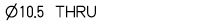
<HoleNoteText name="ThruHole_String" format="^n^$Hole_Diameter THRU"/>
<HoleNoteText name="Cbore_String" format="^br^^v^^n^$CBore_Diameter^x^$CBore_Depth"/>
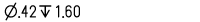
<HoleNoteText name="Csink_String" format="^br^^w^^n^$CSink_Diameter X $CSink_Angle"/>
</HoleNote>
|
HoleNoteText Name
|
Example Format Attribute Content
|
Resulting Example Note
|
|
ThruHole_String
|
^n^&Hole_Diameter THRU
|
|
|
Cbore_String
|
^br^^v^^n^$CBore_Diameter ^x^ $CBore_Depth
|
|
|
Csink_String
|
^br^^w^^n^$CSink_Diameter x $CSink_Angle
|
|
|
HoleNote Name
|
Example Order Attribute Content
|
Resulting Example Note
|
|
ASME-SI Clearance Hole
|
ThruHole_String, Cbore_String, Csink_String
|
|
ASME-US Blind Drilled Hole
<HoleNote name="ASME-US Blind Drilled Hole" order="BlindHole_String,Cbore_String,Csink_String,BlindThread_String">
<HoleNoteText name="BlindHole_String" format="^n^$Hole_Diameter^x^$Hole_Depth"/>
<HoleNoteText name="BlindThread_String" format="^br^^n^$Thread_Diameter-$Threads_Per_Inch $Thread_Series-$Class^x^$Thread_Depth"/>
<HoleNoteText name="Cbore_String" format="^br^^v^^n^$CBore_Diameter^x^$CBore_Depth"/>
<HoleNoteText name="Csink_String" format="^br^^w^^n^$CSink_Diameter X $CSink_Angle"/>
</HoleNote>
|
Element Name
|
Example Format Attribute Content
|
Resulting Example Note
|
|
BlindHole_String
|
^n^$Hole_Diameter ^x^ $Hole_Depth
|
|
|
BlindThread_String
|
^br^^n^$Thread_Diameter-$Threads_Per_Inch $Thread_Series-$Class^x^$Thread_Depth
|
|
|
Cbore_String
|
^br^^v^^n^$CBore_Diameter ^x^ $CBore_Depth
|
|
|
Csink_String
|
^br^^w^^n^$CSink_Diameter x $CSink_Angle
|
<null>
|
|
HoleNote Name
|
Example Order Attribute Content
|
Resulting Example Note
|
|
ASME-US Blind Drilled Hole
|
BlindHole_String, Cbore_String, Csink_String, BlindThread_String
|
|
ISO Thru Drilled Hole
<HoleNote name="ISO Thru Drilled Holes" order="ThruThread_String,BlindThread_String">
<HoleNoteText name="BlindThread_String" format="M$Thread_DiameterX$Pitch-$Class"/>
<HoleNoteText name="ThruThread_String" format="M$Thread_DiameterX$Pitch-$Class THRU"/>
</HoleNote>
|
Note Name
|
Example Format Attribute Content
|
Resulting Example Note
|
|
ThruThread_String
|
M$Thread_Diameter x $Pitch-$Class THRU
|
|
|
BlindThread_String
|
M$Thread_Diameter x $Pitch-$Class
|
|
|
HoleNote Name
|
Example Order Attribute Content
|
Resulting Example Note
|
|
ISO Thru Drilled Hole
|
ThruThread_String, BlindThread_String
|
|
Note that a through hole may have either a through or a blind thread, but of course not both, so the order does not matter for this hole type. The preview panel in the Application Options window displays a preview only for the through thread.
Administrator-defined Notes
You can define an administrator-defined note within the ApplicationNotes element. Each administrator-defined note consists of an AppNoteText element that optionally includes one NoteVariable element. Here is an example:
<AppNoteText name="Example Note" text="ADMINSTRATOR-DEFINED NOTE: $Example_var" display="Optional">
<NoteVariable name="Example_var" type="String"/></AppNoteText>
The AppNoteText element has the following attributes:
• Name – The name of the note that will appear in the notes list in the Edit Part Properties window. This name must be unique with respect to all other note names
• Text – The text that will be included in the note. If you want to include a variable (whose value will be specified by the user when the note is applied), that variable name should be preceded by a '$' symbol.
• Display – You can specify either 'Optional' or 'Required'. Required notes are automatically displayed. The user may elect to display optional notes.
A NoteVariable element is required if a variable is included in the note text. The NoteVariable element has the following attributes:
• Name – The name of the variable.
• Type – The variable type. The type attribute should have one of the following values:
◦ String
◦ Real
◦ Integer
◦ Parameter
All administrator-defined notes will appear on the Properties & Notes tab of the Edit Part Properties window.