Detailed Drawings > Annotating the Drawing > Dimensioning the Model > Inserting Dimensions > About Inserting Dimensions
  
About Inserting Dimensions
A dimension that you create in the Drawing mode is known as a driven dimension. This type of dimension reports a value based upon the references selected when the dimension is created. It is not possible to modify the value of a driven dimension as its value is derived from the position of its references. You cannot use a driven dimension to pass values back to the model, as you can with a driving dimension.
Formats of Added Dimensions
The driven dimensions are of following types:
Type
Description
Example
Standard (New References)
Creates a dimension based on one or two selected references. Depending on the references, the dimension results in an angular, linear, radius, or a diameter dimension.
Common References
Adds dimensions between a common base object and one or more objects.
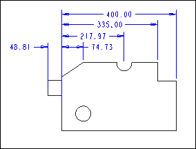
Ordinate
Ordinate dimensions are dimensions that measure a linear distance from an object identified as a baseline.
Auto Ordinate
Automatically creates ordinate dimensions in parts and sheet metal parts.
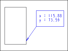
Coordinate Dimension
Lets you assign an existing x- and y- dimension to a label and leader box.
Z-radius
Creates a special radius dimension of an arc that allows you to position an “imaginary” center that is not at the same point as the measured arc’s center. A Z-type jog is automatically added to the dimension line indicating that the dimension line is foreshortened.
Reference Dimensions
All reference dimensions are identical to standard dimensions except that they have special notation that indicates they are reference dimensions. You can use the parenthesize_ref_dim configuration option and set the value to yes to enclose these dimensions in parenthesis. If this option is set to no, the text 'REF” will follow the dimension value.
The following illustrations show reference dimensions.