ECAD-MCAD Collaboration Tutorial 3: Comparing Designs
This tutorial contains 4 exercises. You will move 2 components, and then compare this new design to the baseline design in order to create an incremental IDX file to send to the ECAD designer. You must follow the exercises below sequentially.
Exercise 1: Importing a Baseline IDX File
1. In a new session of Creo Parametric, select the folder where you downloaded the tutorial files, then right-click, and select Set Working Directory.
2. Click  Open.
Open.
Open.3. Click the arrow next to the Type list, then select EDMD (*.idx).
4. Select the baseline_00.idx file from the available files, then click Import. The Import New Model dialog box opens.
5. Leave the Use default template and Component follow board check boxes selected, then click OK. The Holes Handling dialog box opens.
6. Click OK. Baseline_00.ASM opens.
This completes the first of 4 exercises.
Exercise 2: Making Changes to the Baseline Design
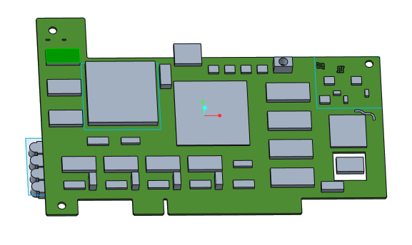
1. Select the first instance of part SOP48.PRT in the Model Tree or graphics window. This part instance is highlighted in the figure below.
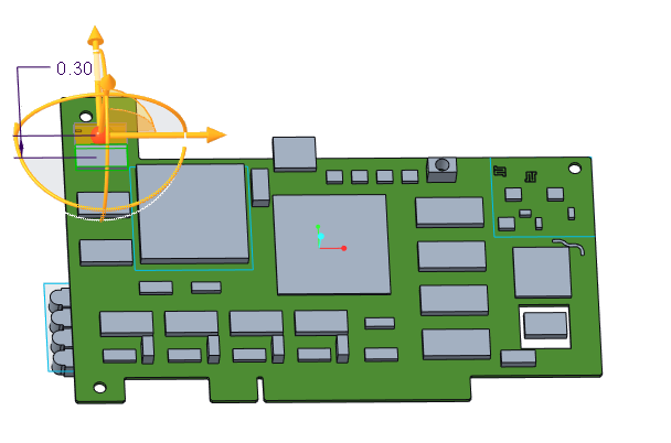
2. On the Model tab, in the Component group, click > >  Dynamic Move. The Move tab opens and the 3D dragger attaches to the component.
Dynamic Move. The Move tab opens and the 3D dragger attaches to the component.3. Drag the arrow on the 3D dragger to 0.30 as in the figure below.
4. Click  OK
OK
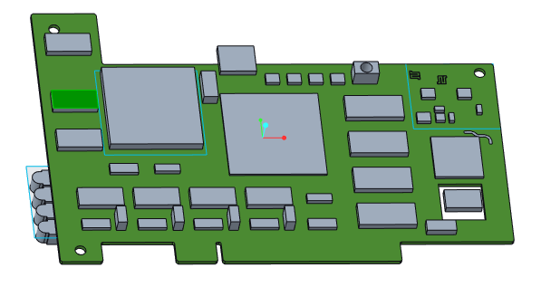
OK5. Select the adjacent component, the second instance of part SOP48.PRT, in the Model Tree or graphics window. This component is highlighted in the figure below.
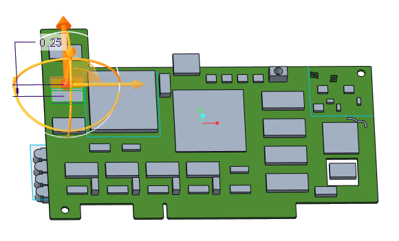
6. Click > > Dynamic Move. The Move tab opens and the 3D dragger attaches to the component.
Dynamic Move. The Move tab opens and the 3D dragger attaches to the component.7. Drag the arrow on the 3D dragger to 0.25 as in the figure below.
8. Click OK.
This completes the second of 4 exercises.
Exercise 3: Comparing Designs
1. Click  ECAD Collaboration. The ECAD-MCAD Collaboration tab opens.
ECAD Collaboration. The ECAD-MCAD Collaboration tab opens.2. Click  Compare. The Open dialog box opens.
Compare. The Open dialog box opens.3. Click the arrow next to the Type list and select ECAD EDA (*.eda).
4. Select the .eda file of the original design, baseline_00.eda and click Open. Creo View ECAD Validate opens.
5. If prompted, click User Info.
6. Enter your user information, then click OK.
7. In the Transaction Summary panel, select any check box. The components that you changed appear in the Transaction List panel.
8. Select the first component in the Transaction List panel.
9. To see the proposed change, click  , the lighter of the 2 icons. The component highlights in its changed location in the Creo Parametric graphics window. The Collaboration area appears under the graphics window.
, the lighter of the 2 icons. The component highlights in its changed location in the Creo Parametric graphics window. The Collaboration area appears under the graphics window.
10. To see the original location of the component, click  , the darker of the 2 icons. The component highlights in a different color, in its original location in the graphics window. The Collaboration area appears under the graphics window.
, the darker of the 2 icons. The component highlights in a different color, in its original location in the graphics window. The Collaboration area appears under the graphics window.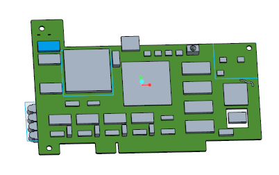
11. In the working directory, the file TempCompareResults.idx, is the incremental IDX file to send to the ECAD designer.
This completes the third of 4 exercises.
Exercise 4: Accepting or Rejecting Changes
1. To accept a change from the baseline design in the updated design, in the Creo View ECAD Validate Transaction List, right-click the modified component and select Set as Accept. The transaction is set as Accept in the Revised column of the Transaction List.
2. Click  in Creo View ECAD Validate to save the accepted and rejected changes as a TempCurModelForCompr.eda file.
in Creo View ECAD Validate to save the accepted and rejected changes as a TempCurModelForCompr.eda file.This concludes Tutorial 3.