ECAD-MCAD Collaboration Tutorial 1: Creating an ECAD Assembly
This tutorial contains 5 exercises. You will create an ECAD assembly and a board. After creating the board, you will add mounting holes and an ECAD area. You will then save the board as an IDX file to send to the ECAD designer.
Exercise 1: Create an ECAD Assembly
In this exercise we will create an ECAD assembly.
1. In a new Creo Parametric session, click  or > New.
or > New.2. From the Type list, select  Assembly.
Assembly.3. From the Sub-type list, select ECAD.
4. In the File name box type ECAD_tutorial.
5. Click OK. A new ECAD assembly opens in the main window.
This completes the first of 5 exercises.
Exercise 2: Creating a Board Part
In this exercise we will import a sketch to create a board part in the ECAD assembly.
1. Click  Create/Edit Board. The Create Board dialog box opens.
Create/Edit Board. The Create Board dialog box opens.2. In the Name box, type the name ECAD_tutorial.
3. Leave the Use default template check box selected.
4. Click OK. The Model tab opens. The board is the active part and options to create the board are available.
5. Click  Planar. The Planar tab opens.
Planar. The Planar tab opens.6. In the Thickness box, type 0.10.
7. In the References tab, click Define.
8. The Sketch dialog box opens. Select the TOP datum plane of the board part as the Sketch Plane. The Reference box populates with the RIGHT datum plane.
9. Click Sketch. The Sketch tab opens.
10. In the Get Data group, click  Import. The Open dialog box opens.
Import. The Open dialog box opens.11. Select the tutorial_sketch.sec sketch and click Open. The sketch is attached to the pointer.
12. Click in the graphics window to place the sketch. Use the  icon to move the sketch in the graphics window.
icon to move the sketch in the graphics window.13. Set the Scaling factor to 1.0.
14. Click  . The sketch of the board displays in the graphics window.
. The sketch of the board displays in the graphics window.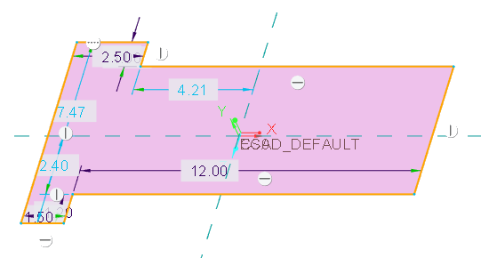
15. Click to accept the sketch.
to accept the sketch.16. Click on the Planar tab. The board appears in the graphics window.
on the Planar tab. The board appears in the graphics window.
This completes the second of 5 exercises.
Exercise 3: Adding Mounting Holes
In this exercise we will add mounting holes to the board part.
1. Click  Hole. The Hole tab opens.
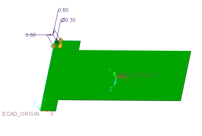
Hole. The Hole tab opens.2. Click the top left corner of the board to place the first hole.
3. Set the hole diameter to 0.3.
4. In the Depth box, click the triangle next to the icon, then select  Through All.
Through All.5. Drag the handles to the edges of the board and set the distance from the edges to 0.6. Reference the figure below.
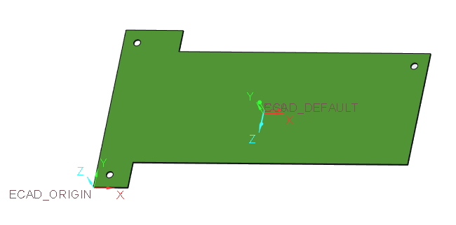
6. Click .
.7. Using the figure below as a reference, add additional holes that are the same distance from the edges of the board to 2 additional corners of the board.
This completes the third of 5 exercises.
Exercise 4: Adding an ECAD Area to the Board Part
In this exercise you will add an ECAD place restriction area to the board surface.
1. Click  ECAD Area. The ECAD Area tab opens.
ECAD Area. The ECAD Area tab opens.2. Leave the default  Place restriction type selected.
Place restriction type selected.3. In the Placement tab, click Define. The Sketch dialog box opens.
4. Select the TOP datum plane of the board part as the Sketch Plane. The Reference box populates with the RIGHT datum plane.
5. Click Sketch. The Sketch tab opens.
6. Click Rectangle and sketch a rectangle as dimensioned in the figure below.
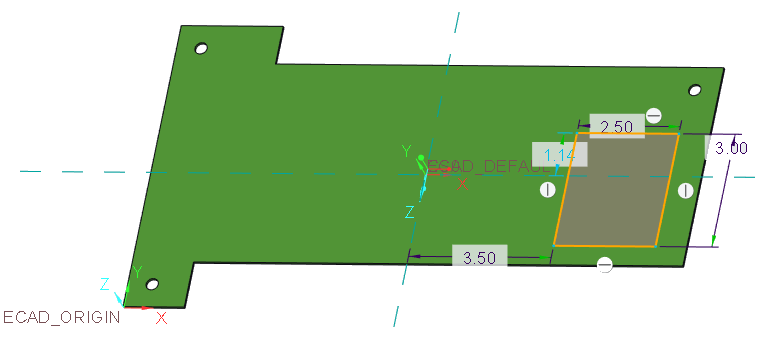
7. Click to accept the sketch.
to accept the sketch.8. Click in the ECAD Area tab. The area is added to the board.
in the ECAD Area tab. The area is added to the board.This completes the fourth of 5 exercises.
Exercise 5: Saving an IDX File for Collaboration
Save the file to send to the ECAD designer.
1. Click >  Save As > .
Save As > .2. Click the arrow next to the Type list, then select EDMD(*.idx) from the list.
3. Leave the name and click OK. The file is saved in the working directory.
This concludes Tutorial 1.