ECAD-MCAD Collaboration Tutorial 2: Importing and Viewing ECAD Context Data
This tutorial contains 3 exercises. You will import ECAD context data, then change its display.
Exercise 1: Importing a Baseline IDX File
In this exercise you will import a baseline IDX file.
1. In a new session of Creo Parametric, select the folder where you downloaded the tutorial files, then right-click, and select Set Working Directory.
2. Click  Open.
Open.
Open.3. Click the arrow next to the Type list, then select EDMD (*.idx) or All.
4. Select the baseline_00.idx file from the available files, then click Import. The Import New Model dialog box opens.
5. Leave the Use default template and Component follow board check boxes selected, then click OK. The Holes Handling dialog box opens.
6. Click OK. Baseline_00.ASM opens.
Under the graphics window, click  to display the Notifications area. Errors, warnings, and log files are shown here when you import files.
to display the Notifications area. Errors, warnings, and log files are shown here when you import files.To turn off datum display in the graphics window, on the graphics toolbar, click  , and then clear the (Select All) check box. , and then clear the (Select All) check box. |
This completes the first of 3 exercises.
Exercise 2: Import ECAD Context Data
In this exercise you will import ECAD context data to the ECAD design.
1. In the open Baseline_00.ASM, click  Import ECAD Context Data. The Import ECAD Context Data dialog box opens.
Import ECAD Context Data. The Import ECAD Context Data dialog box opens.2. Click Open. The Open dialog box opens.
Open. The Open dialog box opens.3. Select the ecaddesign.eda file, then click Open. The file path appears in the box.
4. For this exercise, we will not import all data. Make sure Import selected (recommended) is selected then click Next.
The Select Data To Import page opens.
5. Expand Advanced Search.
6. From the Criteria , select each of the following options, while clicking Add to List after each selection. The order you select these options is not important.
◦ Pin Pads
◦ Routes
◦ Silkscreen
◦ Solder Mask
7. Click Find now. The Search Summary table updates to include only the items you selected.
8. Click Next. The Customize Data Settings page opens.
9. Click Import. An import notification appears.
10. Click Close.
This completes the second of 3 exercises.
Exercise 3 Changing the Display Color of ECAD Context Data
All ECAD context data is imported into the design in the same default color. You can select types of data to change their color, to see it clearly in the design.
1. In the open design, click  ECAD Context Data Explorer. The ECAD Context Data Explorer dialog box opens.
ECAD Context Data Explorer. The ECAD Context Data Explorer dialog box opens.2. From the Top Layer list, select Silkscreen. Press CTRL and select Silkscreen from the Bottom Layer list.
3. Click  (the color button). A color palette appears.
(the color button). A color palette appears.4. From Theme Colors, select the green color  . The color of the silkscreen in the graphics window changes to green.
. The color of the silkscreen in the graphics window changes to green.5. From the Top Layer list, select Solder Mask. Press CTRL and select Solder Mask from the Bottom Layer list.
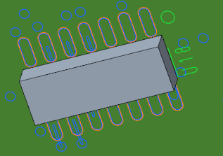
6. From Theme Colors, select the orange color  . The color of the solder masks in the graphics window changes to orange.
. The color of the solder masks in the graphics window changes to orange.7. You can change the color of additional types of ECAD context data.
8. Click Close.
The colors of the solder masks and silkscreens in the design update.
This concludes Tutorial 2.