Creating Extrusions Using the Sketches
1. In the Model Tree, select Sketch 1.
2. On the Model tab, click  Extrude from the Shapes group. The Extrude tab opens.
Extrude from the Shapes group. The Extrude tab opens.3. Click Options and select  To Next from the Side 1 and Side 2 drop-down lists.
To Next from the Side 1 and Side 2 drop-down lists.4. Click  OK.
OK.
OK.5. In the Model Tree, right-click Sketch 1, and click  Show.
Show.
Show.6. Ensure that Sketch 1 is not selected in the Model Tree. On the Model tab, click Extrude from the Shapes group. The Extrude tab opens.
Extrude from the Shapes group. The Extrude tab opens.7. Right-click in the graphics window and click  Define Internal Sketch. The Sketch dialog box opens.
Define Internal Sketch. The Sketch dialog box opens.8. Click Use Previous. The Sketch tab opens.
9. On the Graphics toolbar, click  Display Style, and then click
  Wireframe.
Display Style, and then click Wireframe.10. On the Graphics toolbar, click  Datum Display Filters, and clear the (Select All) check box to clear all datum display check boxes.
Datum Display Filters, and clear the (Select All) check box to clear all datum display check boxes.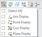
11. On the Graphics toolbar, click  Sketch View.
Sketch View.12. On the Sketch tab, click  Offset from the Sketching group. The mini toolbar opens.
Offset from the Sketching group. The mini toolbar opens.
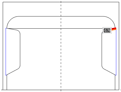
13. To select a partial loop of curves:
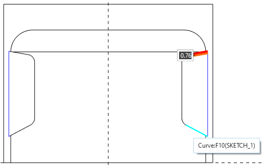
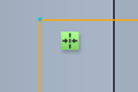
a. In the selection filter at the bottom left of the graphics window, select Curve.
b. Point over the curve at the top of the sketch until it is highlighted. Make sure the tooltip shows Sketch 1. You might need to zoom in and point far to the right on the curve.
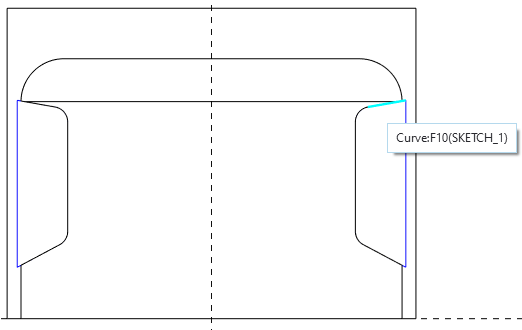
c. Click the highlighted curve to select it.
d. On the mini toolbar, click  . The Chain dialog box opens.
. The Chain dialog box opens.e. Under References, select Rule-based. The curve you selected appears in the Anchor collector.
f. Under Rule, select Partial loop.
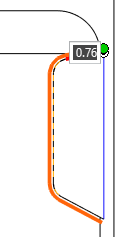
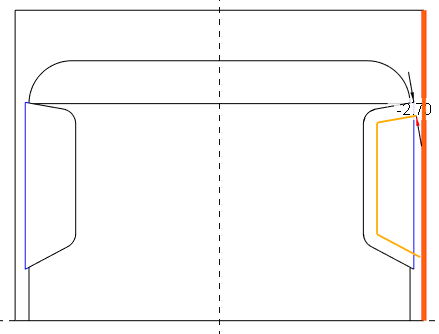
g. Click the Extent Reference collector, and point over the curve at the bottom of the sketch until it is highlighted.
h. Click the highlighted curve to select it. A partial loop of orange offset curves appears from the anchor to the extent reference.
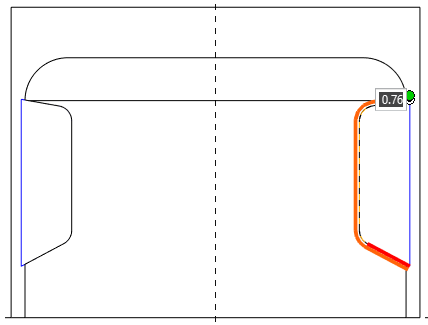
If the partial loop does not go in the direction you intend, click Flip next to Range in the Chain dialog box.
|
14. Type –2.7 in the value box, and press ENTER. The negative value switches the offset curves to the other side of the original curves.
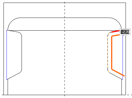
15. In the Chain dialog box, click OK. Three orange sketched entities are created.
16. On the mini toolbar, click  .
.
.
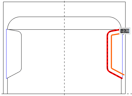
17. On the Sketch tab, click  Project from the Sketching group. The mini toolbar opens.
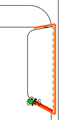
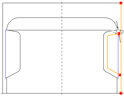
Project from the Sketching group. The mini toolbar opens.18. Select the outer vertical line, which is the boundary of the cylinder. A new orange sketched entity is created on the selected edge.
19. On the mini toolbar, click .
.
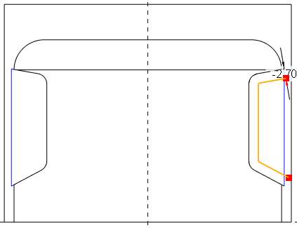
20. On the Sketch tab, click  Corner from the Editing group.
Corner from the Editing group.a. Click the top angled orange entity, and click the right vertical line. The angled and vertical sketched entities are joined.
b. Click the bottom angled orange entity, and click the right vertical line. A closed box is created.
21. Click  Centerline from the Sketching group.
Centerline from the Sketching group.a. Click anywhere on the vertical dashed line.
b. Move the pointer. The centerline is attached to the pointer.
c. Click the vertical dashed line again to define the centerline placement.
22. Click  Select from the Operations group.
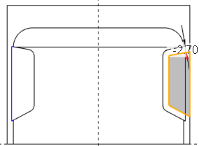
Select from the Operations group.23. Hold down left-mouse button and drag a box around the sketched orange lines.
24. Click  Mirror from the Editing group, and click the vertical centerline.
Mirror from the Editing group, and click the vertical centerline.25. Right-click in the graphics window and choose Save the sketch and exit.
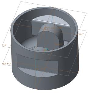
Save the sketch and exit.26. Right-click in the graphics window and choose  Remove Material.
Remove Material.27. In the Extrude tab, do the following:
a. Click the arrow next to  and select Symmetric
  from the list.
and select Symmetric from the list.b. Set the value to 160 and click OK.
OK.28. On the Graphics toolbar, click Display Style, and then click  Shading With Edges.
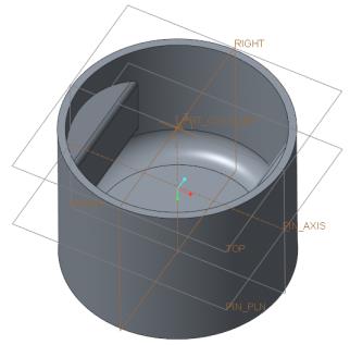
Display Style, and then click Shading With Edges.29. On the Graphics toolbar, click  Saved Orientations, and then click Default Orientation.
Saved Orientations, and then click Default Orientation.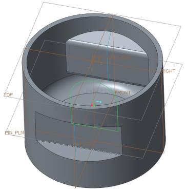
30. On the Model tab, click  Sketch from the Datum group. The Sketch dialog box opens.
Sketch from the Datum group. The Sketch dialog box opens.31. In the Sketch dialog box, do the following:
a. Select the datum plane RIGHT.
b. Click the Reference box and select the inside bottom surface of the piston as shown in following figure.
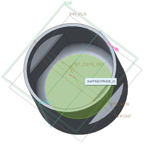
c. Select Top from the Orientation list and click Sketch.
32. Right-click in the graphics window and click References. The References dialog box opens.
33. Select the datum plane PIN_PLN. The datum plane name appears in the box.
34. Click Close to close the References dialog box.
35. On the Graphics toolbar, click Sketch View.
Sketch View.36. Click Centerline from the Sketching group.
Centerline from the Sketching group.a. Click anywhere on the vertical dashed line to define the start of the centerline.
b. Move the pointer and click the vertical dashed line again to finish defining the vertical centerline placement.
37. Click  Rectangle from the Sketching group.
Rectangle from the Sketching group.a. Click anywhere on the bottom horizontal dashed line to define the start point of the rectangle.
b. Drag the pointer up to the second horizontal line.
c. Continue to drag the pointer to the other side of the vertical centerline.
d. Click again when the rectangle snaps to indicate vertical symmetry. Two arrows appear to signify symmetry.
38. Middle-click to exit the draw rectangle tool.
39. Double-click to edit the width dimension value to 28 and press ENTER.
40. Click  Center and Point from the Sketching group.
Center and Point from the Sketching group.a. Click the intersection of the vertical centerline and upper horizontal dashed line to start the circle.
b. Drag the pointer and click again when the circle snaps to the upper vertical sketched vertices of the rectangle.
41. Click  Delete Segment from the Editing group.
Delete Segment from the Editing group.42. Press CTRL and click lines 1, 2, 3, and, 4 as shown in the following figure.
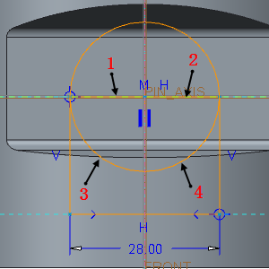
43. Middle-click to exit the delete segment tool.
44. Right-click in the graphics window and click Save the sketch and exit.
Save the sketch and exit.45. Select Sketch 2 in the Model Tree or in the graphics window.
46. On the Model tab, click Extrude from the Shapes group. The Extrude tab opens.
Extrude from the Shapes group. The Extrude tab opens.47. Click Options and select To Next from the Side 1 and Side 2 drop-down list.
To Next from the Side 1 and Side 2 drop-down list.48. Click OK.
OK.49. In the Model Tree, select Sketch 2, and click Extrude. The Extrude tab opens. Remove Material is automatically selected.
Extrude. The Extrude tab opens. Remove Material is automatically selected.50. On the Extrude tab, click the arrow next to , and click Symmetric .
, and click Symmetric .51. Edit the value to 28.7 and press ENTER.
52. Click OK.
OK.