Multiphase Flow for a Fuel Tank: Exercise 3—Preparing the Mesh
Generating the Mesh
1. In the Flow Analysis Tree, select Domains.
2. In the Properties panel, Mesh tab, for Mesh Generation, type the following values:
◦ Maximum Cell Size—0.008
◦ Minimum Cell Size—0.0003
◦ Cell Size on Surfaces—0.002
◦ Create a Refinement Zone—Cylindrical Zone
▪ Cell Size—0.002
▪ Top Circle Center—4.0140, -2.6150, 0.2656
▪ Bottom Circle Center—3.6139, -2.6140, 0.1586
▪ Zone Radius—0.03
3. Click  Generate Mesh to create the mesh for the fluid domain.
Generate Mesh to create the mesh for the fluid domain.Viewing the Mesh
1. Clear  CAD Bodies and enable
  Flow Analysis Bodies.
CAD Bodies and enable Flow Analysis Bodies.2. Press CTRL and under Domains select all the fluid domains. In the View panel, click  Show to display the selected domains.
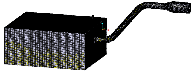
Show to display the selected domains.3. In the Properties panel, View tab, set Grid, and Outline to Yes. The mesh for the domain appears as shown in the figure.
4. In the Properties panel, View tab, set Grid, and Outline to No.
5. In the Post-processing group click . Section View A new entity Section 01 appears under Derived Surfaces in the Flow Analysis Tree.
Section View A new entity Section 01 appears under Derived Surfaces in the Flow Analysis Tree.6. Select Section 01.
7. In the Properties panel, Model tab, set values for the options as listed below:
◦ Type—Plane Y
◦ Position— –2.62 (minus 2.62)
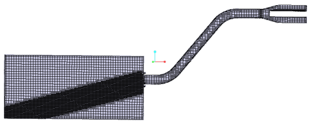
8. In the Properties panel, View tab, for Grid select Yes. The mesh for the section appears as shown in the figure.