Power Inverter without Heat Transfer: Exercise 2—Preparing the Mesh
1. In the Flow Analysis Tree, select Domains.
2. In the Properties panel, Mesh tab, for Mesh Generation, type the following values:
◦ Maximum Cell Size—0.02
◦ Minimum Cell Size—0.0007
◦ Cell Size on Surfaces—0.01
The values are retained as default settings. You can change these if required.
3. Click  Generate Mesh to create the mesh for the fluid domain. If the Info dialog box opens, click Yes to convert all the units.
Generate Mesh to create the mesh for the fluid domain. If the Info dialog box opens, click Yes to convert all the units.4. Click  in the Graphics toolbar to display the style elements. Select
  No Hidden,
  Hidden Line, or
  Wireframe to display the mesh.
in the Graphics toolbar to display the style elements. Select No Hidden, Hidden Line, or Wireframe to display the mesh.5. Clear  CAD Bodies.
CAD Bodies.6. Enable  Flow Analysis Bodies.
Flow Analysis Bodies.7. In the Functions panel click  Turn on/off view properties and select the following from the list:
  Hide all surfaces,
  Hide all grids, and
  Hide all outlines.
Turn on/off view properties and select the following from the list: Hide all surfaces, Hide all grids, and Hide all outlines.8. To view the surface, mesh or outline for a boundary, in the Flow Analysis Tree, under > > select the boundary POWERINVERTER_1_FLUID.
9. In the View panel, click  Show to display the selected boundaries.
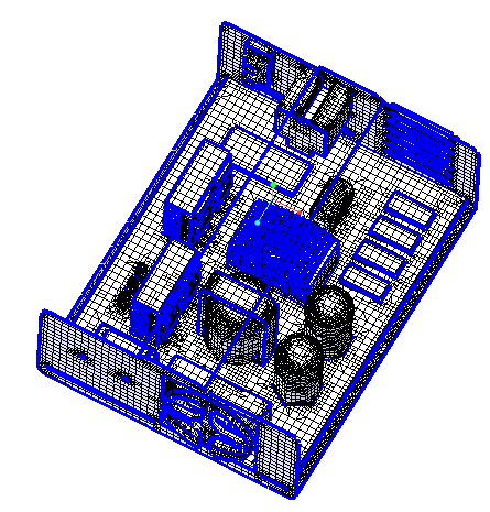
Show to display the selected boundaries.10. In the Properties panel, View tab, set Grid, and Outline to Yes. The mesh for the boundary POWERINVERTER_1_FLUID appears as shown.