Cyclone Separator Exercise 2—Preparing the Mesh
A mesh is a computational grid inside, outside, or both inside and outside any closed geometry defined by a CAD surface.
Generating the Mesh
1. In the Flow Analysis Tree, select Domains.
2. In the Properties panel, Mesh tab, for Mesh Generation, type the following values:

◦ Maximum Cell Size—0.02
◦ Minimum Cell Size—0.0007
◦ Cell Size on Surfaces—0.01
The values are retained as default settings. You can change these if required.
3. Click  Generate Mesh to create the mesh for the fluid domain.
Generate Mesh to create the mesh for the fluid domain.Viewing the Mesh
1. Click  in the Graphics toolbar to display the style elements. Select
  No Hidden,
  Hidden Line, or
  Wireframe to display the mesh.
in the Graphics toolbar to display the style elements. Select No Hidden, Hidden Line, or Wireframe to display the mesh.2. Clear  CAD Bodies.
CAD Bodies.3. Enable  Flow Analysis Bodies.
Flow Analysis Bodies.4. In the Functions panel click  Turn on/off view properties and select the following from the list:
  Hide all surfaces,
  Hide all grids, and
  Hide all outlines.
Turn on/off view properties and select the following from the list: Hide all surfaces, Hide all grids, and Hide all outlines.5. To view the surface, mesh or outline for a boundary, in the Flow Analysis Tree, under  Boundary Conditions >
  General Boundaries > select the boundary CYCLONE_4_FLUID_1.
Boundary Conditions > General Boundaries > select the boundary CYCLONE_4_FLUID_1.6. In the View panel, click  Show to display the selected boundaries.
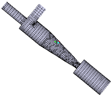
Show to display the selected boundaries.7. In the Properties panel, View tab, set Grid, and Outline to Yes. The mesh for the boundary CYCLONE_4_FLUID appears in the graphics window.