Cavitation over an Orifice: Exercise 2—Preparing the Mesh
1. In the Flow Analysis Tree select Domains.
2. In the Properties panel, Model tab, for Mesh Generation, specify the following values:
◦ Maximum Cell Size—0.005
◦ Minimum Cell Size—0.001
◦ Cell Size on Surfaces—0.005
◦ Create a Refinement Zone—Cylindrical Zone
▪ Cell Size—0.0025
▪ Top Circle Center—0.0140, 0, 0
▪ Bottom Circle Center—0.032, 0, 0
Zone Radius—0.006
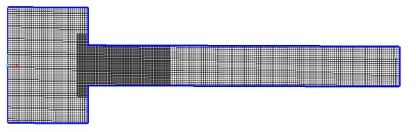
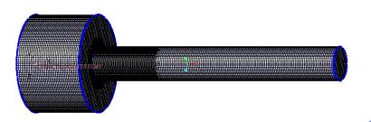
3. Click  Generate Mesh to create the mesh for the fluid domain. If the Info dialog box opens, click Yes to convert all the units.
Generate Mesh to create the mesh for the fluid domain. If the Info dialog box opens, click Yes to convert all the units.4. Click  in the Graphics toolbar to display the style elements. Select
  No Hidden,
  Hidden Line, or
  Wireframe to display the mesh.
in the Graphics toolbar to display the style elements. Select No Hidden, Hidden Line, or Wireframe to display the mesh.5. Clear  CAD Bodies.
CAD Bodies.6. Enable  Flow Analysis Bodies.
Flow Analysis Bodies.7. In the Functions panel click  Turn on/off view properties and select the following from the list:
  Hide all surfaces,
  Hide all grids, and
  Hide all outlines.
Turn on/off view properties and select the following from the list: Hide all surfaces, Hide all grids, and Hide all outlines.8. To view the surface, mesh or outline for a boundary, in the Flow Analysis Tree, under > select the boundary ORIFICE_CAVITATION.
9. In the View panel, click  Show to display the selected boundary.
Show to display the selected boundary.10. In the Properties panel, View tab, set Grid, and Outline to Yes. The mesh for the boundary ORIFICE_CAVITATION appears in the graphics window.