Defining a Part Loop
If the Stackup is defined between features on two different parts, the Assembly area opens in the New Stackup dialog box.
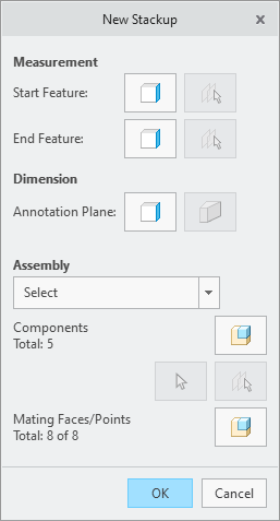
This step in the process of defining a new Stackup involves identifying the parts that are included in the Stackup and the mating features that control how those parts are connected. This is referred to as the part loop.
Creo EZ Tolerance Analysis offers two methods of identifying the part loop. The automatic method is when the software can find a path between the start and end features of the Stackup using the assembly constraints defined in the model. The manual method is when the user selects the parts and mating features to define the part loop.