Automatic Detection and Selection of the Parts in the Loop and Interacting Surfaces
In the New Stackup dialog box, under Assembly, if Assembly Constraints is selected, then at least one path from the assembly constraints is found between the two parts at either end of the Stackup definition. There may be more than one available path listed in the dialog.
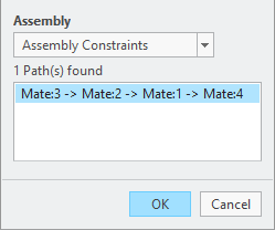
1. Select each of the paths. The parts involved in the loop appear in the graphics window. Any parts not involved in the loop are hidden.The features on each of the parts that are used as assembly constraints are highlighted.The path represents the assembly constraints that are used for the Stackup definition.
2. Select the required path and click OK.
3. If none of the paths are correct, select the pull-down menu and pickSelect to define the path manually.