Example: Analyzing the Reflectivity of a Lamp Shade
Summary: This example shows how to use a UDA to analyze some reflection properties of a lamp shade.
Problem: Need to analyze the angle at which the light is reflected from of the surfaces of a lamp shade.
Solution: Measure the reflection angle using the analysis features. Then you can create a UDA to apply the value of the reflection angle to the entire surface.
Follow these basic steps to create the UDA:
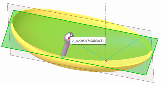
1. Create a field point on the surface. Click > > >
2. Define an axis that passes through this field point and is normal to the surface. Click > You can use this axis to evaluate the angle and apply the condition that the angle of incidence must be equal to the angle of reflection.
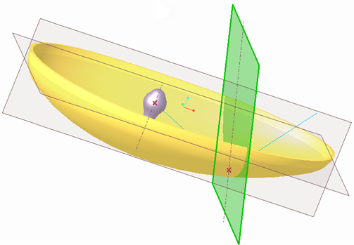
3. Create a datum plane passing through the field point and the axis A4 of the lamp. Click OK.
4. Click > Create a new datum plane crossing through the datum plane axis and normal to the datum plane.
5. Click > select reference as LENS and DTM1 from the Model Tree, and click Sketch.
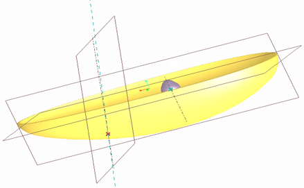
6. Change the orientation of the field point and face the lamp downwards.
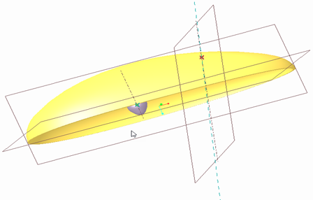
7. In the graphic window, right-click and select References. From the status bar, select a datum point and click a datum point of the lamp. Select the axis from the status bar, and then click  to update the sketch. Click Close.
to update the sketch. Click Close.8. Click Line and draw a datum curve from the LAMP point to the field point and draw another point higher than the LAMP point. The vertex of the curve to the right must be vertically aligned to the LAMP point. The two curves must be equal.
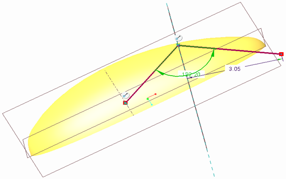
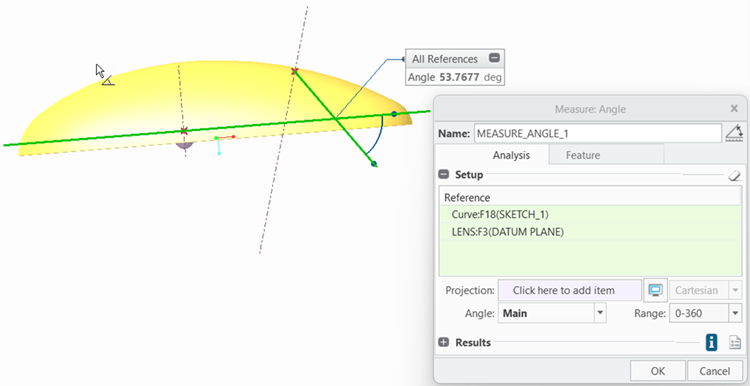
9. Define an analysis feature to measure the angle. Click > > Select the datum plane LENS and the datum curve created in the previous step. Click OK.
10. Create a LOCAL_GROUP in the Model Tree. Select the field point, axis, datum planes, and datum curve, right-click, and then select Group.
Only one field point is allowed in the construction group, and it must be the first feature, whereas an analysis must be the last feature. |
11. Click >
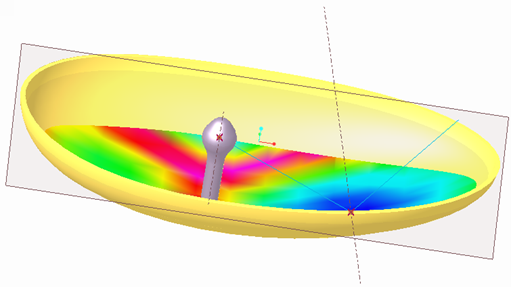
12. Click Compute from the User Defined Analysis dialogue box. To save this analysis in an analysis feature, click Add Feature and enter the name for the feature. A new analysis feature appears on the Model Tree.
13. Click Close.