Example: Automatic Assembly Using Declared Datums
This example shows how to use a reference datum plane and axis for automatic assembly of a bolt to all three holes in a flange. The sketch of the bolt and flange is only an illustration with no dimensions.
First a notebook is created with a datum plane and a datum axis.

1. Datum plane BOLT_HEAD
2. Datum axis BOLT_AXIS
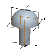
The notebook is declared to the bolt part, then the datum plane and axis are declared to the corresponding axis and plane in the bolt.

1. Declared datum plane
2. Declared datum axis
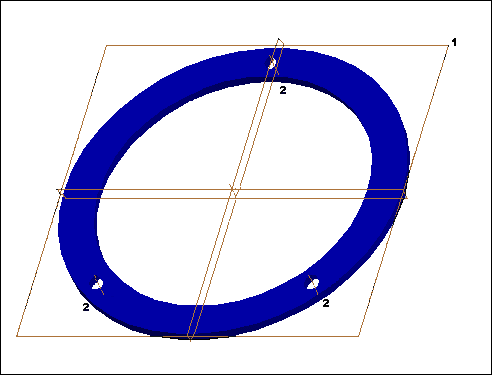
The notebook is declared to the flange part. Since all three holes will be used for component placement and the same references are used to place each occurrence of the bolt, a table declaration is used.
The axis for each hole in the flange is declared to the BOLT_AXIS datum axis while the datum plane as the surface of the flange is declared for each hole. See the table below for placement definitions for each hole in the flange.


1. Declared datum plane
2. Declared datum axes
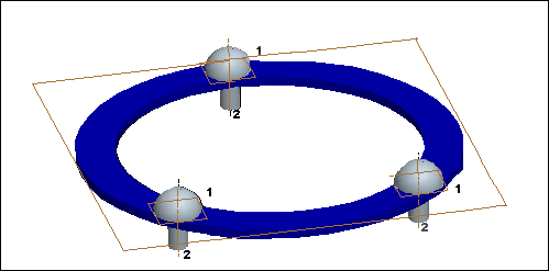
The bolts are automatically assembled in the three holes.

1. Declared datum plane BOLT_HEAD
2. Declared datum axes BOLT_AXIS