Turbulent Flow in Diffuser: Exercise 1—Setting up the Model
Extracting the Fluid Domain
1. Click > and navigate to the folder with the downloaded parts. Click OK.
2. Click >  Open.
Open.
Open.3. From the File Open dialog box, browse to the diffuser folder and select diffuser.asm. Click Open.
4. Click  in the Graphics toolbar to display the style elements. Select Shading, or
  Shading with Edges.
in the Graphics toolbar to display the style elements. Select Shading, or Shading with Edges.5. Click the Applications tab.
6. Click  Flow Analysis. The Flow Analysis tab opens.
Flow Analysis. The Flow Analysis tab opens.7. Click  New Project. The New Project dialog box opens. Click OK to create a new project Project 1.
New Project. The New Project dialog box opens. Click OK to create a new project Project 1.8. Click  Select Simulation Domains. The Domain Model Selection box opens.
Select Simulation Domains. The Domain Model Selection box opens.9. In the Domain Model Selection box, select Add fluid domain.
10. In the Model Tree select DIFFUSER.PRT.
11. Middle-click to confirm. The fluid domain appears in the Domain Model Selection dialog box under Fluid Components.
12. Click OK. The fluid domain appears in the Flow Analysis Tree, as DIFFUSER under Domains.
Adding Boundary Conditions
1. Under Domains, right-click and select DIFFUSER.
2. In the graphics window, select the inner surface highlighted in red below.
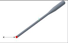
3. Click OK. Under General Boundaries, a new entity BC_00001 is added.
4. Under Domains, right-click and select DIFFUSER.
5. In the graphics window, select the outer surface highlighted in blue below.
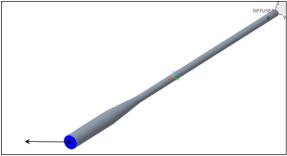
6. Click OK. Under General Boundaries, a new entity BC_00002 is added.
7. Right-click and rename the following boundary conditions:
◦ BC_00001 as inlet
◦ BC_00002 as outlet
Parent topic