2D-3D Contact Analysis Problems
This chapter contains 2D and 3D contact problems and Creo Simulate's results. In a contact analysis, Creo Simulate calculates deformations, stresses, and strains on your model in response to specified loads and subject to specified constraints. Creo Simulate also automatically calculates all predefined measures. This list of measures differs based on the analysis type.
This chapter contains the following contact problems:
mvsc001: 2D Contact-Hertz Contact
|
Analysis Type:
|
2D Contact
|
|
Model Type:
|
Plane Strain
|
|
Comparison:
|
Theory
|
|
Reference:
|
Roark, R.J. and Young, W. Formula for Stress and Strain. NY; McGraw-Hill Co. 1982. p. 517.
|
|
Description:
|
A half model of two cylinders of unit depth in contact. Modeled using 2D contact. Determine the maximum stress and contact area.
|

Specifications
Element Type: | 2D solid | |
Units: | IPS | |
Dimensions: | R1: 1 R2: 1 | |
Material Properties: | Mass Density: 0 Cost Per Unit Mass: 0 Young's Modulus: 1e6 | Poisson's Ratio: 0.3 Thermal Expansion: 0 Conductivity: 0 |
Constraints: | fixed in all but y on vertical edges; fixed in all but x on bottom edge | |
Loads: | -1000 on top element edges (symmetry): Total Load=-2000 | |
Comparison of Results Data
Theory | Structure | % Difference | |
|---|---|---|---|
Contact Area | 0.0481 | 0.0481 | 0% |
Maximum Stress (m=contact_max_press) | 26450 | 26353.88 | 0.363% |
Convergence %: 0.8 % on Contact Area and Contact Pressure | Max P: 9 | No. Equations: 397 | |
mvsc002: 3D Contact-Hertz Contact
Analysis Type: | 3D Contact |
Model Type: | 3D |
Comparison: | Theory |
Reference: | Roark, R.J. and Young, W. Formula for Stress and Strain. NY; McGraw-Hill Co. 1982. p. 517. |
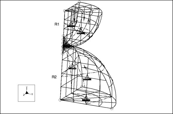
Description: | A quarter section of two hemispheres in contact. Determine the maximum stress and contact area. |

Specifications
Element Type: | 2D solid | |
Units: | IPS | |
Dimensions: | R1: 2 R2: 3 | |
Material Properties: | Mass Density: 1 Cost Per Unit Mass: 1 Young's Modulus: 1e7 | Poisson's Ratio: 0.3 Thermal Expansion: 1 Conductivity: 1 |
Constraints: | fixed in all but y on xz face; fixed in all but x on yz face; fixed on bottom edge | |
Loads: | -25000 on top element faces (symmetry): Total Load=-100000 | |
Comparison of Results Data
Theory | Structure | % Difference | |
|---|---|---|---|
Contact Area | 0.0507 | 0.0481 | 7.692% |
Maximum Stress (m=contact_max_pres) | 740285 | 742075.3 | 0.241% |
Convergence %: 1.6 % on measure convergence | Max P: 9 | No. Equations: 6192 | |
mvsc003: Sliding and rolling of a ring on a rigid surface
Analysis Type: | 2D contact |
Model Type: | 2D Plane Strain |
Comparison: | NAFEMS Benchmark |
Reference: | Benchmark tests for finite element modelling of contact, gap and sliding, Ref:- R0081, Issue: 1, CGS - 7, PP 53. |
Description: | The problem consists of a simple 2D model with finite friction subjected to prescribed displacement. |

1. contact interface
Specifications
Element Type: | 2D solid | |
Units: | mmNs | |
Dimensions: | R: 500 mm | |
Material Properties: | Mass Density: 7850 kg/m^3 Young's Modulus: 210 GPa | Poisson's Ratio: 0.3 |
Constraints: | The steel ring is fixed along X- axis. | |
Loads: | G = 2443 N Prescribed displacement x= 785 mm on bottom edge of the plate | |
Coefficient of Friction | μ=1.0 | |
Comparison of Results Data
NAFEMS | Structure | % Difference | |
|---|---|---|---|
Rotation in the ring in degree (m = rotation_ring) | 90 | 89.9 | 0.1 % |
mvsc004: Interfaces between two cylinders
Analysis Type: | 2D contact |
Model Type: | 2D Axisymmetric |
Comparison: | NAFEMS Benchmark |
Reference: | Benchmark tests for finite element modelling of contact, gap and sliding, Ref:- R0081, Issue: 1, CGS - 10, PP 61. |
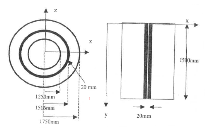
Description: | The problem consists of a simple 2D contact problem with 20 mm interference. Average contact pressure is computed. |

1. interference
Specifications
Element Type: | 2D Solid | |
Units: | mmNs | |
Dimensions: | As shown in the figure above | |
Material Properties: | Mass Density: 0 Young's Modulus: 206E9 N/m^2 | Poisson's Ratio: 0.0 |
Constraints: | The top and bottom of the two cylinders are constraint in the vertical direction. | |
Loads: | A dummy load is applied on extreme left edge. | |
Comparison of Results Data
NAFEMS | Structure | % Difference | |
|---|---|---|---|
Contact Pressure in N/m^2 (m = pressure_avg) | 2.275E8 | 2.346E8 | 3 % |
mvsc005: Sliding wedge
Analysis Type: | 2D contact |
Model Type: | 2D Axisymmetric |
Comparison: | NAFEMS Benchmark |
Reference: | Benchmark tests for finite element modelling of contact, gap and sliding, Ref:- R0081, Issue: 1, CGS - 4, PP 47. |
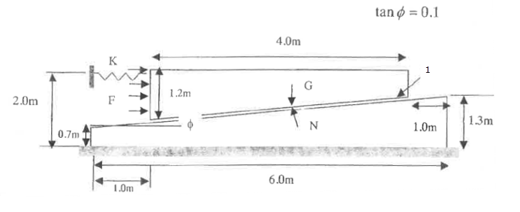
Description: | The problem consists of a simple 2D model with finite friction. |

1. contact interface
Specifications
Element Type: | 2D Solid | |
Units: | MKS | |
Dimensions: | As shown in the figure above | |
Material Properties: | Mass Density: 0 Young's Modulus: 206 GPa | Poisson's Ratio: 0.3 |
Constraints: | The bottom of the foundation is constrained in all directions. The left side of the wedge is connected to 9 linear springs (stiffness 98 N/m) in the horizontal direction. The other end of the springs are constrained in all directions. | |
Loads: | F = 1500 N G = 3058 N | |
Coefficient of Friction | μ= 0.1 | |
Comparison of Results Data
NAFEMS | Structure | % Difference | |
|---|---|---|---|
Horizontal Displacement (m = displacement_x) | 1.0 | 1.0 | 0 % |