油箱多相流动:练习 3 - 准备网格
生成网格
1. 在 Flow Analysis 树中,选择“域”(Domains)。
2. 在“属性”(Properties) 面板的“网格”(Mesh) 选项卡中,为“网格生成”(Mesh Generation) 键入以下值:
◦ “最大单元大小”(Maximum Cell Size) - 0.008
◦ “最小单元大小”(Minimum Cell Size) - 0.0003
◦ “曲面单元大小”(Cell Size on Surfaces) - 0.002
◦ “创建细化区域”(Create a Refinement Zone) -“圆柱区域”(Cylindrical Zone)
▪ “单元大小”(Cell Size) - 0.002
▪ “顶部圆心”(Top Circle Center) - 4.0140, -2.6150, 0.2656
▪ “底部圆心”(Bottom Circle Center) - 3.6139, -2.6140, 0.1586
▪ “区域半径”(Zone Radius) - 0.03
3. 单击  “生成网格”(Generate Mesh) 为流体域创建网格。
“生成网格”(Generate Mesh) 为流体域创建网格。查看网格
1. 清除  “CAD 主体”(CAD Bodies) 并启用
  “Flow Analysis 主体”(Flow Analysis Bodies)。
“CAD 主体”(CAD Bodies) 并启用 “Flow Analysis 主体”(Flow Analysis Bodies)。2. 按住 CTRL 键并在“域”(Domains) 下选择所有流体域。在“视图”(View) 面板中,单击  “显示”(Show) 以显示所选域。
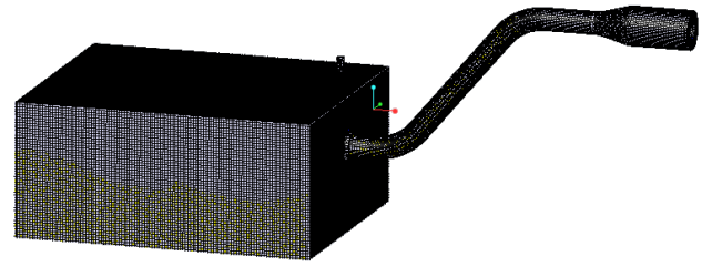
“显示”(Show) 以显示所选域。3. 在“属性”(Properties) 面板的“视图”(View) 选项卡中,将“网格”(Grid) 和“轮廓”(Outline) 设置为“是”(Yes)。此时会显示域的网格,如图所示。
4. 在“属性”(Properties) 面板的“视图”(View) 选项卡中,将“网格”(Grid) 和“轮廓”(Outline) 设置为“否”(No)。
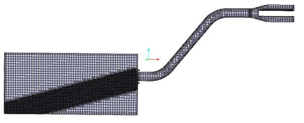
5. 在“后处理”(Post-processing) 组中单击  “剖视图”(Section View)。新要素 Section 01 将显示在 Flow Analysis 树中的“衍生曲面”(Derived Surfaces) 下。
“剖视图”(Section View)。新要素 Section 01 将显示在 Flow Analysis 树中的“衍生曲面”(Derived Surfaces) 下。6. 选择 Section 01。
7. 在“属性”(Properties) 面板的“模型”(Model) 选项卡中,设置以下选项值:
◦ “类型”(Type) -“平面 Y”(Plane Y)
◦ “位置”(Position) - -2.62 (负 2.62)
8. 在“属性”(Properties) 面板的“视图”(View) 选项卡中,为“网格”(Grid) 选择“是”(Yes)。此时会显示截面的网格,如图所示。