Power Inverter without Heat Transfer: Exercise 1—Extracting the Fluid Domain
1. Click > and navigate to the FlowAnalysisModels folder. Click OK.
2. Click >  Open.
Open.
Open.3. From the File Open dialog box, browse to the power_inverter_assembly_creo folder and select powerinverter.asm. Click Open.
4. Click  in the Graphics toolbar to display the style elements. Select Shading, or
  Shading with Edges.
in the Graphics toolbar to display the style elements. Select Shading, or Shading with Edges.5. Click the Applications tab.
6. Click  Flow Analysis. The Flow Analysis tab opens.
Flow Analysis. The Flow Analysis tab opens.7. Click  New Project. If the Residual plot opens, close it.
New Project. If the Residual plot opens, close it.8. Click  Create Fluid Domain. The Fluid Domain Creation tab opens.
Create Fluid Domain. The Fluid Domain Creation tab opens.9. Select the Shrinkwrap check box.
10. Click the Openings tab.
11. Click the Faces box. The Surface Sets dialog box opens.
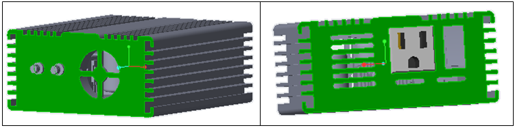
12. Press CTRL and select the two surfaces as shown below.
13. Click OK in the Surface Sets dialog box.
14. Click  .
.
.15. Click  Select Simulation Domains. The Domain Model Selection box opens.
Select Simulation Domains. The Domain Model Selection box opens.16. In the Domain Model Selection box, select Add fluid domain.
17. In the Model Tree select POWERINVERTER_FLUID_1.PRT. Middle-click to confirm. The fluid domain appears in the Domain Model Selection dialog box under Fluid Components.
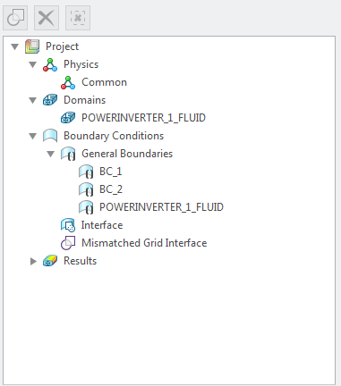
18. Click OK. The fluid domain appears in the Flow Analysis Tree as POWERINVERTER_FLUID_1:Body 1. Boundaries for the boundary conditions BC_00001, BC_00002, and POWERINVERTER_FLUID_1:Body 1 are automatically created. They appear in the Flow Analysis Tree under General Boundaries in the Boundary Conditions area.
19. Under Domains, right-click POWERINVERTER_1_FLUID_DOMAIN and select  Add Boundary Condition. The Surface Sets dialog box opens.
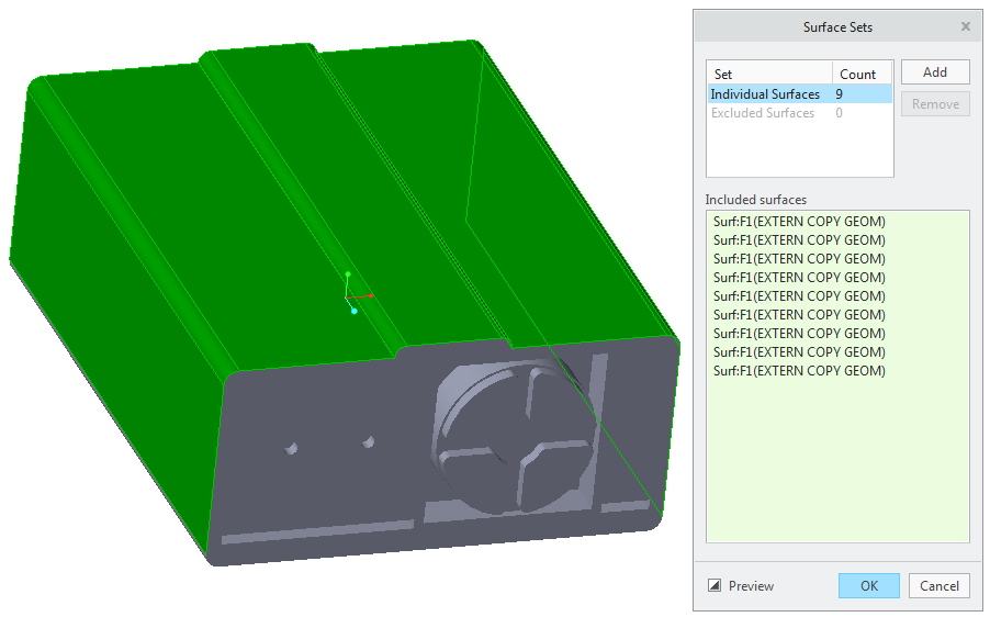
Add Boundary Condition. The Surface Sets dialog box opens.20. Press CTRL and select the nine surfaces on the upper side of the inverter as shown in the figure below.
21. Click OK. Under General Boundaries a new entity BC_00003 is created.