Moving Geometry
In this exercise, you learn to move geometry using a dragger, and using dimensions. You explore different ways to attach the moved geometry to the model. This exercise includes the following tasks:
Move using the dragger—basic
In this task, you will move geometry with  Move using Dragger.
Move using Dragger.1. In Creo Parametric, set the working directory to <downloaded files location>, and open sp115050.prt.
2. To disable all datum display filters, click  Datum Display Filters on the in-graphics toolbar, and clear all the check boxes.
Datum Display Filters on the in-graphics toolbar, and clear all the check boxes.3. To set the display style, click  Display Style on the in-graphics toolbar, and select
  Shading With Edges.
Display Style on the in-graphics toolbar, and select Shading With Edges.4. To set the model view, click  Saved Orientations on the in-graphics toolbar, and select VIEW 1.
Saved Orientations on the in-graphics toolbar, and select VIEW 1.5. Click the Flexible Modeling tab.
6. In the graphics window, select the blue surface, parallel to the top surface of the non-cylindrical hole.
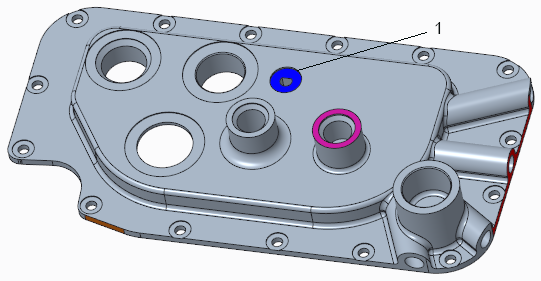
1. Blue surface
7. To select the entire cut of which the selected surface is a part, along with smaller surfaces that intersect it, in the Shape Surface Selection group, click  Cuts.
Cuts.
Cuts.8. To view the selected surfaces more closely, click Saved Orientations, and select VIEW 2.
Saved Orientations, and select VIEW 2.9. To select the desired geometry:
a. Press and hold down the CTRL key while you select the yellow outer surface of the cylinder.
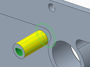
b. To select the entire boss of which the selected surface is a part, in the Shape Surface Selection group, click  Boss.
Boss.
Boss.Now all the geometry that you want is selected.
10. To view the front of the model, click Saved Orientations, and select FRONT.
Saved Orientations, and select FRONT.11. To select the type of move, in the Transform group, click the arrow under Move, and select Move using Dragger. The Move tab opens.
Move, and select Move using Dragger. The Move tab opens.12. To move the geometry, drag the handle of the dragger to the position shown below.
13. Click  to accept the feature.
to accept the feature.Move by dimensions
In this task, you will use  Move by Dimension to make the model shorter by moving a surface, three holes, and their associated geometry.
Move by Dimension to make the model shorter by moving a surface, three holes, and their associated geometry.1. Click Saved Orientations on the in-graphics toolbar, and select VIEW 3.
Saved Orientations on the in-graphics toolbar, and select VIEW 3.2. In the lower right corner of the Creo window, ensure that the selection filter is Regions and Surfaces.
3. To select the geometry to move (three holes on the left side of the model, their associated geometry, and the left side of the model):
a. Select the planar surface of the upper left hole.
b. To select the entire cut of which the selected surface is a part, along with smaller surfaces that intersect it, in the Shape Surface Selection group, click Cuts.
Cuts.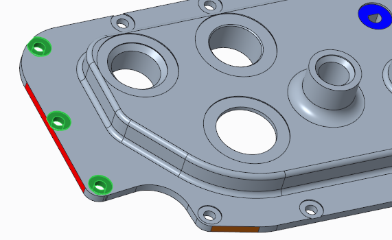
c. Press and hold down the CTRL key while you select the planar surface of the middle left hole, and then click Cuts.
Cuts.Alternately, to use the mini toolbar, hold down CTRL while you select the surface, and then temporarily release the CTRL key to click Cuts on the mini toolbar. |
d. Continue holding down the CTRL key while you select the planar surface of the lower left hole, and then click Cuts.
Cuts.e. Continue holding down the CTRL key while you select the red surface on the left side of the part, next to the holes.
4. In the Transform group, click the arrow under Move, and select Move by Dimension. The Move tab opens.
Move, and select Move by Dimension. The Move tab opens.5. To set the dimension, on the Move tab, click the Dimensions tab, and do the following:
a. To select the references for the dimension, click the References collector, and then press and hold down the CTRL key while you select the left side surface of the model, and the right side surface.
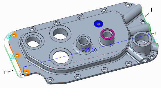
1. Side surfaces
b. To set the dimension value, click the Value collector, and change the value from 228 to 220.
Notice how the holes remain in position during the move.
6. Click to accept the feature.
to accept the feature.Move using a dragger, use bounding edges, and navigate multiple solutions
In this task, you will move geometry with Move using Dragger, use bounding edges to drive the solutions, and navigate multiple solutions.
Move using Dragger, use bounding edges to drive the solutions, and navigate multiple solutions.1. Click Saved Orientations on the in-graphics toolbar, and select VIEW 4.
Saved Orientations on the in-graphics toolbar, and select VIEW 4.2. Select the purple surface.
3. To select the entire boss of which the selected surface is a part, along with smaller surfaces that intersect it, in the Shape Surface Selection group, click  Bosses.
Bosses.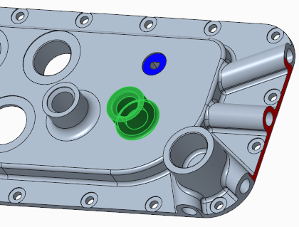
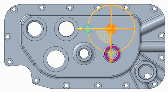
4. To select the type of move, click the arrow under Move, and select Move using Dragger. The Move tab opens, and the dragger appears on the selected geometry.
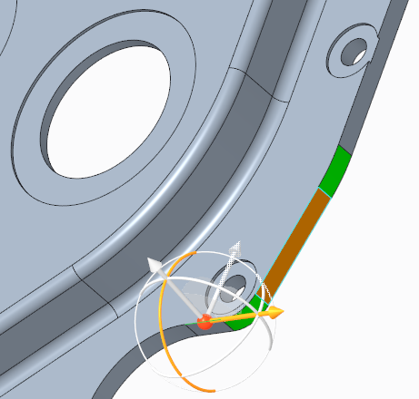
Move, and select Move using Dragger. The Move tab opens, and the dragger appears on the selected geometry.5. To place the dragger, click the edge to the right, as shown:

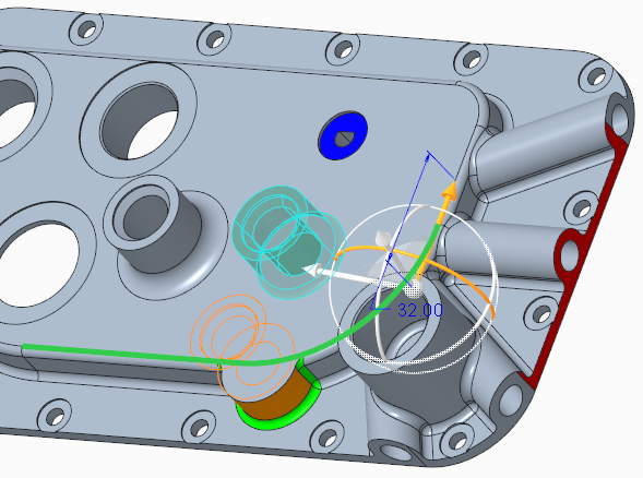
6. To move the selected geometry:
a. Drag the handle of the dragger downwards, toward the larger boss in the bottom right corner.
b. In the graphics window, click the offset value and edit it to 32.
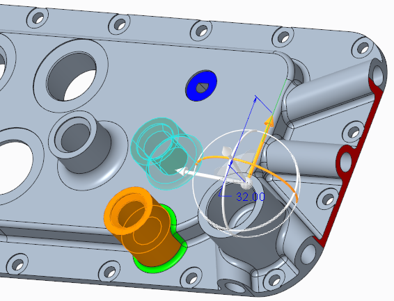
Notice how the solution automatically recreates the rounds, even though the topology under the boss has changed.
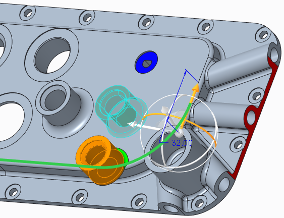
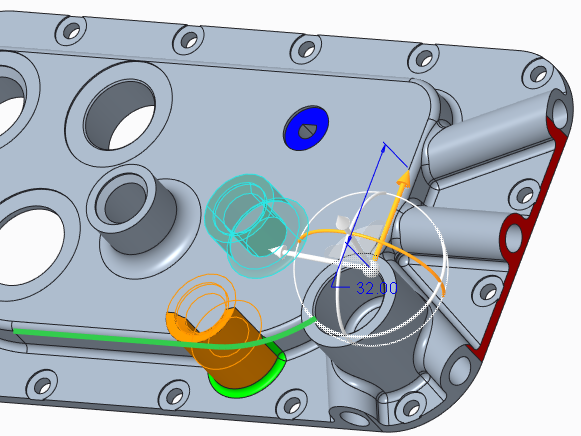
7. To select bounding edges:
a. Click the Attachment tab.
b. Click the Bounding edges collector.
c. Press and hold down the CTRL key while you select the two tangent edges where the top round connects to the top planar surface, and that pass through the preview of the moved geometry.
8. To see what other solutions are available, on the Attachment tab, click Next. The system uses the surfaces adjacent to the bounding edges to extend and intersect the moved geometry in the various solutions.
9. To select different bounding edges:
a. To remove the selected bounding edges, in the Bounding edges collector, right-click and choose Remove All.
b. Press and hold down the CTRL key while you select the two tangent edges where the top round connects to the vertical planar surface, parallel to the two edges you selected previously, but farther down.
10. To see what other solutions are now available, on the Attachment tab, click Next. Now the vertical surface below the selected edge is extended.
11. Use this solution, and click .
.
Attachment options
In this task, you will get to know different types of attachment options in the context of a move using a dragger. During a move in Creo Flexible Modeling, click  to create side surfaces to fill the gap between the moved surface and the neighboring geometry.
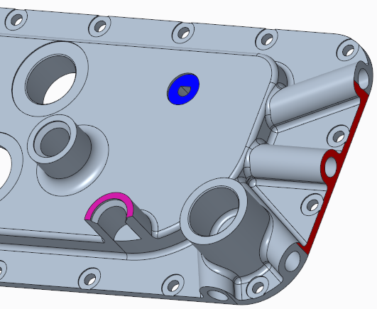
to create side surfaces to fill the gap between the moved surface and the neighboring geometry.1. Click Saved Orientations on the in-graphics toolbar, and select VIEW 5.
Saved Orientations on the in-graphics toolbar, and select VIEW 5.2. Select the orange surface.
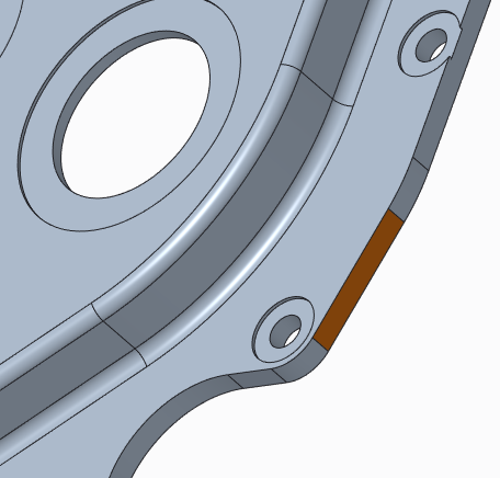
3. To select the type of move, click the arrow under Move, and select Move using Dragger. The Move tab opens.
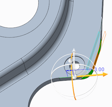
Move, and select Move using Dragger. The Move tab opens.4. To place the dragger, click the edge where the horizontal and vertical surfaces connect.
5. To move the selected geometry:
a. Drag the handle of the dragger to move the geometry to the right.
b. Edit the offset value to 3.
6. Click to activate the attachment options.
to activate the attachment options.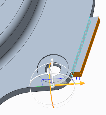
7. Click again to view a different attachment option.
again to view a different attachment option.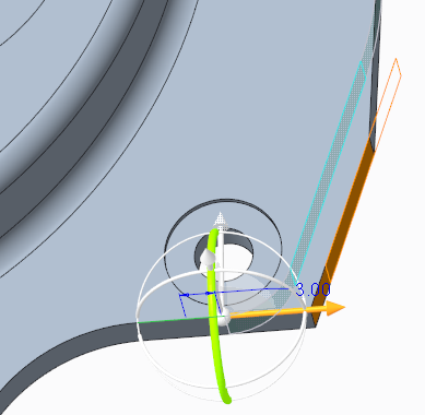
8. Click to accept the feature.
to accept the feature.9. Save and close the model.