Example—External Fluid Simulation in Creo Simulation Live
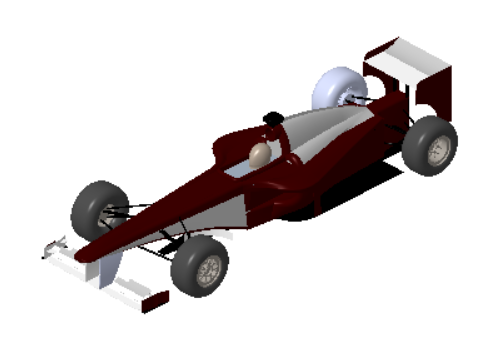
In a simulation of an external fluid flow, a model is positioned inside an enclosure. Fluid flows through the enclosure and around the model. To study this flow use an External Fluid Flow simulation study. Consider the following example of a racing car.
In this example an enclosure is created around the car. The enclosure represents a virtual wind tunnel through which the air flows. To try out the example, download the sample assembly model from here. Extract the compressed file SimLiveExampleExternalFluidSimulation.zip to a local folder. Open the assembly model f1_car.asm.
To run an external fluid flow simulation study, perform the following steps:
1. Click Live Simulation. Click >  Fluid Simulation Study. Click the arrow next to Study and select the Transient Mode check box. A fluid simulation study node with the default name Fluid1 (transient) is created and listed in the Simulation Tree.
Fluid Simulation Study. Click the arrow next to Study and select the Transient Mode check box. A fluid simulation study node with the default name Fluid1 (transient) is created and listed in the Simulation Tree.2. Click >  Enclosure Volume. The Enclosure Volume tab opens.
Enclosure Volume. The Enclosure Volume tab opens.3. Click Offsets. Add linear offsets for all the enclosure surfaces except the ground surface. In this example the offset for the surface in front of the car is 1.0. The offset value from the back of the car is 2.5. The offset from the top, and the two side surfaces is 0.5. The offset from the ground surface is 0.
Linear Offset | Value |
|---|---|
+X | 0.5 |
-X | 0.5 |
+Y | 0.5 |
-Y | 0 |
+Z | 1 |
-Z | 2.5 |
All offsets are in the assembly system of units which is MKS/SI in this example. If you use any other system of units, convert the offsets as required.
See the topic “To Define an Enclosure Volume” in the Related Links at the end of this topic for more details on how to define an enclosure volume.
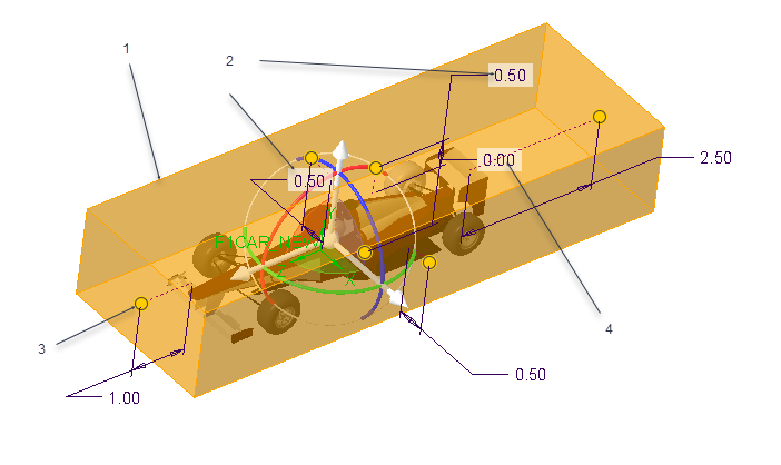
1. Enclosure volume
2. Edit offset value.
3. Pull dragger to change offset value
4. Offset from car to ground is 0
Click OK. A transparent volume enclosure is created around the car as shown below. Use the configuration option enclosure_volume_transparency to change the transparency of the enclosure. Valid values are from 0 to 1. The default value is 0.92. (92 percent). A higher value means a more transparent enclosure volume.
4. The fluid domain appears in the Simulation Tree. Right-click and select Edit Materials. The Materials dialog box opens. Select air.mtl from the Fluid Material folder in the Materials directory. Click OK to assign a material to the enclosure volume.
5. Assign the following boundary conditions to the model:
◦ Flow Velocity—Click > . Select the enclosure face in front of the car. Select Directional components. Specify a value of –25 m/sec for the value of velocity in the Z- direction.
◦ Outlet Pressure—Click >  Outlet Pressure. Select the opposite face of the enclosure. and specify a value of 0 Pa.
Outlet Pressure. Select the opposite face of the enclosure. and specify a value of 0 Pa. Slip Symmetry
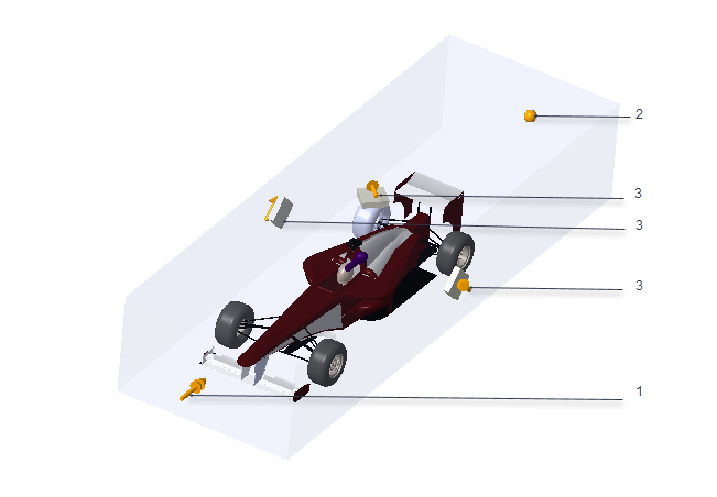
1. Define flow velocity for the inlet surface
2. Define outlet pressure at the outlet surface
3. Slip symmetry applied to the two side surfaces and the top surface
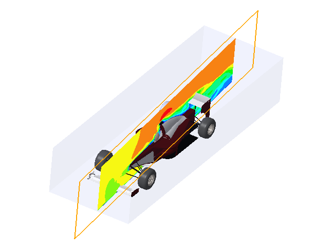
6. Click  Simulate to start the live simulation. Live results of the fluid analysis are displayed in the graphics window.
Simulate to start the live simulation. Live results of the fluid analysis are displayed in the graphics window.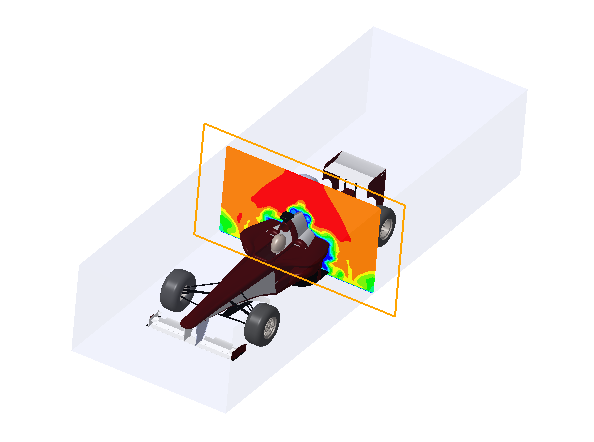
Use various display options to control the way results appear and to explore variations of the results. In the following figure the cut plane has been rotated by 90 degrees.