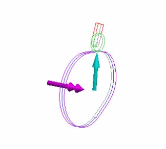
Example: Load Transfer for a Cam Assembly
The figure below shows the playback of a dynamic analysis of a cam-follower assembly. The green arrows represent the magnitude and direction of the measures created for the analysis. The double-headed magenta arrow represents the net load on the servo motor, and the cyan arrow represents the normal force exerted on the cam.

When you create the load set to transfer to Creo Simulate, the dialog box lists several loads, including forces on the pin joint, and gravity. For this example, only the cam load and the servo motor load were selected. The cam load includes both normal and tangential forces on the cam, but in this analysis, the tangential force is zero.
The figure below shows the cam part opened in Creo Simulate. When the Mechanism Dynamics loads are imported, two datum points are created to apply the loads. The datum point for the cam load is created at the contact point between the two cams at the selected time. The datum point for the servo motor is created at the zero point for the servo motor. After the loads are imported, icons are displayed on the part showing the direction and magnitude of the imported loads.
