Using Gear Pairs in Mechanism Dynamics Analyses
The presence of a gear pair in your mechanism can affect the results of an analysis in which mass is taken into account. Each gear in a gear pair contains one rigid body, called a gear, a rack or a pinion, and a second rigid body called the carrier, connected by a motion axis. One way to ensure that the geometry in your gear pair maintains the desired spatial orientation during an analysis is to use the same rigid body as the carrier body for both gears. This can be ground or another rigid body in the mechanism. The figure shows a simple standard gear pair in which the two parts used for the carrier bodies (red blocks) belong to the same rigid body.
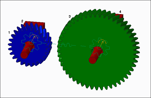
1. Gear 1
2. Carrier 1
3. Gear 2
4. Carrier 2
If you create a gear pair in which the gears do not have a common carrier body, it can affect the results of a dynamic, force balance, or static analysis. The software creates an invisible internal body for gear pairs without a common carrier body. This rigid body is assigned a mass equal to 0.001 (the mass of the smallest rigid body) in the assembly. When you run a dynamic, force balance, or static analysis, a message may appear stating that one of the gear-pair connections does not have a common carrier body. Using the mass of the invisible internal body may adversely affect your analysis results. In this case, stop the analysis and redesign your mechanism so that the gear pair includes a common carrier body. Otherwise, you can continue the analysis with the invisible internal body.
(the mass of the smallest rigid body) in the assembly. When you run a dynamic, force balance, or static analysis, a message may appear stating that one of the gear-pair connections does not have a common carrier body. Using the mass of the invisible internal body may adversely affect your analysis results. In this case, stop the analysis and redesign your mechanism so that the gear pair includes a common carrier body. Otherwise, you can continue the analysis with the invisible internal body.