Global Mesh Size Control—Creo Ansys Simulation
The Global Mesh Size control allows you to control the global mesh sizing and properties. Click > to open the Mesh Control tab. Click  Global Mesh Size to open the Global Mesh Size dialog box.
Global Mesh Size to open the Global Mesh Size dialog box.The global mesh size is controlled by the “Size Function” in the Ansys mesher. You control the mesh size based on the function that you choose from one of the following options for the Size Function method. The values you specify are passed to the solver and define the mesh size based on the method and related properties described below.
• Curvature—Examines curvature on edges and faces and computes element sizes on these entities such that the size does not violate the maximum size or the curvature normal angle, which are either computed automatically by the mesher or user-defined. You can modify the following curvature options to change the element size:
◦ Minimum size—The minimum size of an element. Some element sizes may be smaller than this based on local feature sizes or other geometric anomalies. Specify a value greater than 0 or accept the default.
◦ Maximum face size—The maximum face size that is passed to the mesher. Element faces may be larger than this size based on hard edge sizes or floating point arithmetic. Specify a value greater than 0 or accept the default.
◦ Maximum size—The maximum size that is passed to the mesher. Specify a value greater than 0 or accept the default.
◦ Growth rate—Represents the increase in element edge length with each succeeding layer of elements. For example, a growth rate of 1.2 results in a 20% increase in element edge length with each succeeding layer of elements. The valid values are real numbers between 1 and 5.
◦ Curvature normal angle—The maximum allowable angle that one element edge is allowed to span. Specify a positive non-zero value of up to 180 degrees or 3.14 radians, or accept the default. A smaller value implies a finer mesh.
In the following example (for demonstrative purposes only) figure 1 shows a mesh generated with a Curvature normal angle of 180 degrees and figure 2 shows a mesh generated with a Curvature normal angle of 30 degrees.
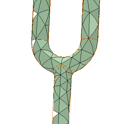 Figure 1–Curvature Normal Angle =180 degree | 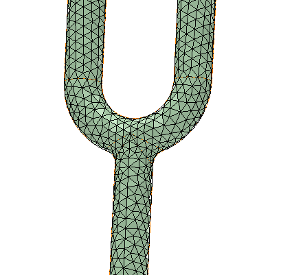 Figure 2–Curvature Normal Angle=30 degree |
• Proximity—Enables you to specify the number of mesh elements employed in the gaps between two geometric entities (proximity size function). Gaps can be defined in two ways:
◦ The internal volumetric region between two faces.
◦ The area between two opposing boundary edges of a face.
The size function controls how the mesh size is distributed on a surface or within a volume. Specify the following options:
◦ Minimum size—The globally allowed minimum element size.
◦ Maximum face size—The global maximum allowable size of the elements created by the free surface meshers when generating apart-based mesh.
◦ Maximum size—The globally allowed maximum element size.
◦ Proximity size function source—Determines whether regions of proximity between faces and/or edges are considered when proximity size function calculations are performed. Choose one of the following:
▪ Edges—Considers edge-edge proximity. Face-face and face-edge proximity are not considered.
▪ Faces—This is the default. Considers face-face proximity between faces. Face-edge and edge-edge proximity are not considered
▪ Faces and edges—Considers face-face and edge-edge proximity. Face-edge proximity is not considered.
◦ Growth rate—Represents the increase in element edge length with each succeeding layer of elements. For example, a growth rate of 1.2 results in a 20% increase in element edge length with each succeeding layer of elements. Specify a value from 1.0 to 5.0 or accept the default. The default is 1.85.
◦ Number of cells across gap—This is the minimum number of layers of elements to be generated in the gaps. You can specify a value from 1 to 100 or accept the default. The default is 1.
• Fixed—The fixed size function does not refine the mesh based on curvature or proximity. You specify minimum and maximum sizes and gradation is provided between sizes based on the specified growth rate. The following properties define the fixed size function:
◦ Minimum size—The minimum size that is passed to the mesher. Some element sizes may be smaller than this based on local feature sizes or other geometric anomalies. Specify a value greater than 0 or accept the default.
◦ Maximum face size—The maximum size that the size function will return to the surface mesher. Element faces may be larger than this size based on hard edge sizes or floating point arithmetic. Specify a value greater than 0 or accept the default.
◦ Maximum size—The maximum size that the size function passes to the mesher. Specify a value greater than 0 or accept the default.
◦ Growth rate—Represents the increase in element edge length with each succeeding layer of elements. For example, a growth rate of 1.2 results in a 20% increase in element edge length with each succeeding layer of elements. Specify a value from 1.0 to 5.0 or accept the default. The default is 1.85.
• Curvature and proximity—Examines curvature on edges and faces as well as allows you to specify the number of mesh elements employed in the gaps between two geometric entities. These properties provide more precise control over mesh size distribution during meshing tasks:
◦ Minimum size—The minimum size that the size function returns to the mesher. Some element sizes may be smaller than this based on local feature sizes or other geometric anomalies. Specify a value greater than 0 or accept the default.
◦ Maximum face size—The maximum size that the size function will return to the surface mesher. Element faces may be larger than this size based on hard edge sizes or floating point arithmetic. Specify a value greater than 0 or accept the default.
◦ Maximum size—The maximum size that the size function returns to the mesher. Specify a value greater than 0 or accept the default.
◦ Proximity size function source—Can have the following values:
▪ Faces—This is the default. Considers face-face proximity between faces. Face-edge and edge-edge proximity are not considered.
▪ Edges—Considers edge-edge proximity. Face-face and face-edge proximity are not considered.
◦ Growth rate—Represents the increase in element edge length with each succeeding layer of elements. For example, a growth rate of 1.2 results in a 20% increase in element edge length with each succeeding layer of elements. Specify a value from 1.0 to 5.0 or accept the default. The default is 1.85.
◦ Curvature normal angle—The maximum allowable angle that one element edge is allowed to span. Enter a non-zero positive value of up to 180 degrees or 3.14 radians, or accept the default.
◦ Number of cells across gap—The minimum number of layers of elements to be generated in the gaps. You can specify a value from 1 to 100 or accept the default. The default is 1.
Saving Global Mesh Settings
The default values of the Global Mesh Size dialog box for a study are governed by the value of the Mesh Resolution control and the model size. When you click OK the default values in the Global Mesh Size dialog box are updated to the user defined values, and thereafter are not automatically calculated for the study. A Global Mesh Size sub-node is added to the Simulation Tree under the Mesh Controls node.
Restoring the Default Settings for Global Mesh Size
When you open the Global Mesh Size dialog box and then click OK, a Global Mesh Size sub-node is added to the Simulation Tree under the Mesh Controls node. To restore the default global mesh size settings for a study, select the Global Mesh Size sub node from the Simulation Tree, right-click and select  Delete.
Delete.