Editing Corner Seams
Use the Edit Corner Seam tool to edit existing corner seams, introduce new corner seams by selecting relevant geometry in your model, or remove existing corner seams. When you edit corner seams, you can set a new shape and removal method of the sides.
Follow the steps below to edit corner seams.
Selecting Corner Seams
1. In an open sheet metal part with corner seams, click >  Edit Corner Seam. The Edit Corner Seam tab opens.
Edit Corner Seam. The Edit Corner Seam tab opens.2. Select the corner reliefs to edit, or click  Automatic to select corner reliefs automatically.
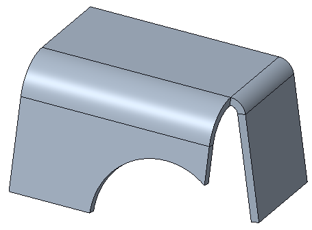
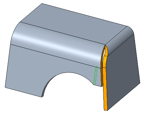
Automatic to select corner reliefs automatically.The figure below shows a corner seam that is selected to edit.
Changing the Type of Corner Seam
1. To remove selected corner seams, click  Remove Corner Seam.
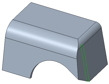
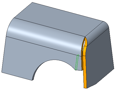
Remove Corner Seam.The figure below shows the corner seam above removed.
2. To change the corner seam type, select an option from the list on the Seam Type list, or the Shape tab. In the Shape tab, an illustration for each option shows the resulting corner seam.
◦ Open—Edits the selected corner seams to Open. You can close the corner.
◦ Blind—Edits the selected corner seams to Blind. Define the width of the gap for each side of the corner seam.
◦ Gap—Edits the selected corner seams to Gap. Define the width of the gap.
◦ Overlap—Edits the selected corner seams to Overlap. Click  Add Gap Dimension or Add gap to define a gap and set its width. Click
  or Flip to flip the side of the corner seam that overlaps.
Add Gap Dimension or Add gap to define a gap and set its width. Click or Flip to flip the side of the corner seam that overlaps.◦ [<Parameter Value>]—Uses the SMT_DFLT_EDGE_TREA_TYPE parameter value.
Removing and Recreating a Corner Seam
To select boundary surfaces to remove, use the Options tab.
1. Select a corner seam from the Corner Seams list.
2. Click the Seam boundary surfaces collector and select up to 2 references.
3. To automatically edit corner reliefs, click to select the Apply V Notch type check box. The adjacent corner reliefs are edited to the V Notch type.
4. To specify whether to recreate round or chamfer geometry adjacent to the edited corner seam, click the Create round/chamfer geometry check box. Rounds or chamfers are recreated in the new location.
5. To define the each side, click to select the Define each side separately check box.
6. Select the side to define.
7. To set a removal method, click to clear the Default removal check box.
8. Select a method from the Removal Method list.
◦ Tangent—Extends or trims the bounding surface making it a planar surface tangent to original surface
◦ Same—Extends or trims the bounding surface by continuing past its original boundaries and keeping the same type of surface.
◦ Parallel—Extends or trims the bounding surface parallel to the bend axis.
◦ Normal—Extends or trims the bounding surface normal to the corner.
◦ Common Vertex—Finds the common vertex for intersection of both bounding surfaces.
Setting Properties
To change feature properties, use the Properties tab.
1. To edit the feature name, type a new one in the Name box.
2. To display information on the feature in the browser, click  .
.
.