About Attached Flat and Flange Walls
Attached Flat Walls
Starting in Creo Parametric release 6.0 when you create an attached Flat wall, neighboring walls are automatically detected. Corner seams and reliefs sometimes are applied to neighboring walls when possible. You can change the geometry created using the options available in the Corner Treatment and Relief tabs. This functionality is not available for flat walls created in a version earlier than Creo Parametric release 6.0.
An attached flat wall is dependent on a first wall. It has any flat shape with a linear attachment edge. An attached flat wall requires an open loop sketch that is extruded as a flat section. From Creo Parametric 8.0 you can create multiple flat walls at the same time. All walls created in the same feature have the same shape. You can create an attached flat wall shape for your design using one of the following methods:
• Select one of the standard flat shapes.
• Sketch a user-defined flat shape.
• Import a predefined flat wall shape.
When you create a user-defined flat shape, you create a feature section. To use this section for multiple flat walls, use the Convert command to convert it to a 2D sketch that is no longer parametric.
For an attached flat wall, click >  Flat.
Flat.
Flat.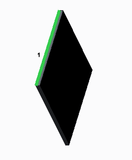 1. Attachment edge | 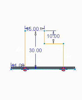 | 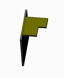 |
Existing walls with selected edge | Flat wall sketch with an open loop | Completed flat wall |
Flange Walls
A flange wall is an attached secondary wall, dependent on a first wall. It has an open cross-sectional sketch that is extruded or swept along a trajectory. An attachment edge can be linear or nonlinear. The surface adjacent to the attachment edge does not need to be planar. You can create a flange wall shape for your design using one of the following methods:
• Select one of the standard flange shapes, including a hem-shaped flange.
• Sketch a user-defined flange shape.
• Import a predefined flange wall shape.
For a flange wall, click >  Flange.
Flange.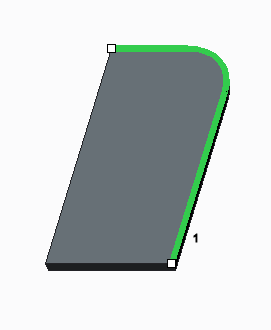 1. Attachment trajectory | 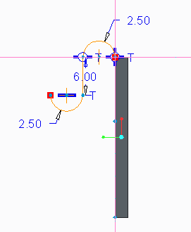 | 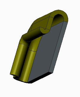 |
Existing wall with selected edges | Flange wall sketch | Completed flange wall |