About the Lattice Feature User Interface
The Lattice tab consists of commands, tabs, and shortcut menus. Click > >  Lattice to open the Lattice tab.
Lattice to open the Lattice tab.Commands
• Lattice Type
◦ Lattice type list
▪  Beams—Creates lattice using 3D cells that contain beams arranged into structures, that are propagated in a pattern.
Beams—Creates lattice using 3D cells that contain beams arranged into structures, that are propagated in a pattern.▪  2.5D—Creates lattice by projecting a planar shape perpendicular to the plane as the lattice cell, and propagating the cell to fill the defined area.
2.5D—Creates lattice by projecting a planar shape perpendicular to the plane as the lattice cell, and propagating the cell to fill the defined area.▪  Formula Driven—Creates lattice using a formula to define the cell shape.
Formula Driven—Creates lattice using a formula to define the cell shape.▪  Custom—Creates lattice using a part that you create in Creo Parametric and import into the Lattice feature to define the lattice cell shape.
Custom—Creates lattice using a part that you create in Creo Parametric and import into the Lattice feature to define the lattice cell shape.▪  Open Cell—Imports the part to use as a cell for a custom designed lattice feature.
Open Cell—Imports the part to use as a cell for a custom designed lattice feature.• Cell Direction
◦ Direction list—Defines the cell alignment direction of the z-axis. You can select Z, X, or Y.
• Cell Propagation
◦ Propagation list—Defines how the cells are positioned in the internal volume for beam-based and 2.5D lattice.
▪ Regular—Fills the volume layer by layer.
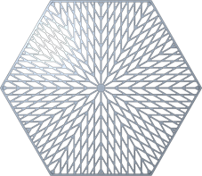
▪ Quasi-radial—Fills the volume in a circular pattern.
▪ Base cell number—Sets the number of cells in a single circle.
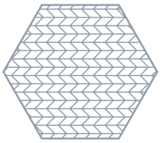
▪ Herringbone—Fills the volume in zigzag pattern.
Skewing angle 30º | Skewing angle 45º |
 |  |
• Cell Scale—Sets the size of the cell relative to its current cell size, keeping its current proportions.
• Options
◦ Representation—Defines the lattice representation.
▪ Full geometry—Creates full lattice geometry that includes all properties and an accurate appearance.
▪ Simplified—Creates a light-weight approximation of the lattice.
▪ Homogenized—For beams lattice, creates a special quilt to represent the lattice volume, to use for analyses in Creo Simulate.
▪ Volumetric—In formula-driven lattice, creates volumetric lattice.
▪ Accuracy—Sets the level of accuracy of the volumetric lattice representation.
Tabs
• Lattice Region
◦ Replace body with lattice check box
▪ When the check box is cleared—Adds lattice inside a volume that you define by selecting bounding surfaces, quilts, and datum planes.
The following options are available:
▪ Lattice volume region collector—Displays the surfaces, quilts, and datum planes that define the volume of the lattice.
▪ Details—Lists the bounding surfaces sets.
▪ When the check box is selected—Replaces the selected body with lattice.
The following options are available:
▪ Body to replace collector—Displays the body to replace with lattice.
▪ Create shell check box—Includes the shell of the body as a part of the lattice. When this option is selected, the following options become available:
▪ Thickness—Controls the thickness of the shell.
▪ Shell side—Controls the direction in which the shell is created. You can choose Inside or Outside.
▪ Excluded shell surfaces collector—Displays the surfaces that are excluded from the shell.
▪ Details—Displays the relevant surface sets.
◦ Skip failed geometry check box—Does not add lattice elements in places where geometry fails. Not available for formula-driven lattice.
◦ Orientation—Selects a coordinate system or a build direction analysis to define the orientation of the lattice.
◦ First cell position collector—Selects a coordinate system as the location for the first lattice cell. The automatically selected location is the origin of the default coordinate system.
• Cell Type
Use this tab to define the cell parameters.
◦ For beam-based lattice, these options are available:
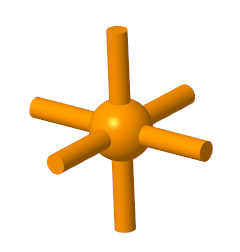
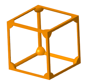
▪ Cell Shape—Defines the shape of the lattice cell.
▪  Triangular
Triangular▪  Square
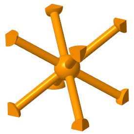
Square▪  Hexagonal
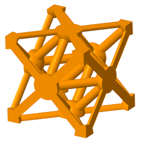
Hexagonal▪  Octagonal
Octagonal▪  Stochastic—Creates lattice by connecting randomly distributed points with beams inside volumes or over surfaces.
Stochastic—Creates lattice by connecting randomly distributed points with beams inside volumes or over surfaces.▪ Cell size—Defines the X, Y, and Z dimensions of the cell. These are the absolute cell dimensions, using the model units.
▪ Skewing angle—Defines the angle of cell slanting.
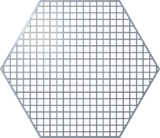
◦ For 2.5D lattice, these items are available:
▪ Cell shape—Defines the shape of the lattice cell.
▪ Triangular
Triangular▪ Square
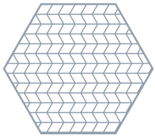
Square▪ Hexagonal
Hexagonal▪  Octagonal
Octagonal▪ Cell size—Defines the X and Y dimensions of the cell. These are the absolute cell dimensions, using the model units.
▪ Skewing angle—Defines the angle of cell slanting.
◦ For formula-driven lattice, these items are available:
▪ Function—Defines the formula that drives the shape of the lattice cell for formula-driven lattice.
▪ Cell size—Defines the X, Y, and Z dimensions of the cell. These are the absolute cell dimensions, using the model units.
◦ For custom lattice, these items are available:
▪ —Imports the part to use as a cell for a custom designed lattice feature.
—Imports the part to use as a cell for a custom designed lattice feature.▪ Cell size—Defines the X, Y, and Z dimensions of the cell. These are the absolute cell dimensions, using the model units.
▪ Fixed scale—Defines the cell scale in relation to its size when you import it for custom lattice.
◦ For stochastic lattice, these items are available:
▪ Algorithm
▪ Delaunay triangulation—Generates the lattice using Delaunay triangulation.
▪ Voronoi diagram—Generates the lattice using Voronoi diagrams.
▪ Stochastic lattice location
▪ Volume + bounding surfaces—Creates lattice over the bounding surfaces and in the inside volume of the model.
▪ On bounding surfaces—Creates lattice over the bounding surfaces of the model.
▪ Inside volume—Creates lattice in the inside volume of the model.
▪ Stochastic cell definition
▪ Cell definition method
▪ Target cell size—Defines the lattice cell size measured diagonally across the bounding box of the cell.
▪ Number of cells—Sets the target number of cells in the lattice structure.
▪ Min. beam length—Sets the minimum length for lattice beams.
▪ Max. beam length—Sets the maximum length for lattice beams.
▪ Randomize—Recalculates the random distribution of the points on which the lattice structure is based.
▪ Trabecular shape check box
—For Voronoi stochastic lattice, reduces the variation in cell size.
• Cell Fill
For beam-based lattice, use this tab to define and display the beams:
◦ Cell configuration—Sets the internal structure of the cell.
▪ Custom—Enables you to select combinations. For triangular-, square-, or hexagonal-type lattice, controls the internal structure of the cell by defining which types of beams are included in or excluded from the structure.
▪ Inner horizontal beams
▪ Inner vertical beams
Inner horizontal beams and inner vertical beams used together
▪ Outer horizontal beams
▪ Outer vertical beams
Outer horizontal beams and outer vertical beams used together
▪ Angular beams
▪ Outer truss beams
▪ Inner truss beams
▪ Clear all—Clears all beam types.
▪ Star—Selects only Angular beams.
▪ Truss—Selects only Outer truss beams and Inner truss beams. Available for Square and Triangular cell shapes.
◦ Dangling beams—Defines how to handle beams that are not attached at both ends to the lattice or to solid geometry.
▪ Keep—Keeps all dangling beams.
▪ Remove—Removes all dangling beams.
▪ Remove by surfaces—Removes the dangling beams at the selected surfaces.
▪ Surfaces collector—Collects surfaces that define open boundaries.
▪ Details—Opens the Surface Sets dialog box.
◦ Ball diameter—When Straight profile is selected, you can add balls at the corners where the beams intersect, and in the center of the cell, and set their sizes.
◦ Round radius check box—Creates rounds at the concave edges between the lattice balls and beams, and defines the radius value. The round radius is ignored for lattice with varied density. Available for Full geometry representation.
◦ Cross section type—Defines the shape of the cross section of the beam.
◦ Cross section size—Defines the size of the cross section of the beam.
◦ Profile type—Defines the shape of the beam.
▪ Straight
▪ Parabolic
▪ Parabolic radius—Sets the parabolic radius.
▪ Profile coefficient—Sets the coefficient of the profile.
For 2.5D lattice, these items are available:
◦ Wall thickness—Sets the thickness of the cell walls.
◦ Round radius check box—Creates rounds at the concave edges of the cells, and defines the radius value. Available for Full geometry representation.
◦ Add drain holes—Adds slot-shaped holes to the cells in 2.5D lattice.
▪ Width—Defines the width of the drain hole.
▪ Length—Defines the length of the drain hole.
▪ Spacing—Defines the distance between two drain holes.
For formula-driven lattice, these items are available:
◦ Wall thickness—Sets the thickness of the cell walls.
◦ Unattached geometry—Defines how to handle geometry that is not attached to the lattice or to solid geometry at intersections with the volume region, due to trimming the lattice cell.
▪ Keep—Keeps all unattached geometry.
▪ Remove—Removes all unattached geometry.
For stochastic lattice, these items are available:
◦ Ball diameter—Adds balls where the beams intersect and in the center of the cell, and set their sizes.
◦ Trim boundary—Trims the beams at the boundary of the lattice.
◦ Cross section size—Defines the size of the cross section of the beam.
◦ Dangling beams—Defines how to handle beams that are not attached at both ends to the lattice or to solid geometry.
▪ Keep—Keeps all dangling beams.
▪ Remove—Removes all dangling beams.
▪ Remove by surfaces—Removes the dangling beams at the selected surfaces.
▪ Surfaces collector—Collects surfaces that define open boundaries.
▪ Details—Opens the Surface Sets dialog box.
• Density
◦ Variability based on
▪  Uniform—Creates lattice with density that does not vary.
Uniform—Creates lattice with density that does not vary.▪  References—Creates lattice with density that varies based on the distance from references. Available for beam-based and formula-driven lattice.
References—Creates lattice with density that varies based on the distance from references. Available for beam-based and formula-driven lattice.▪ Beam-based
▪ Beams
Beams▪ Variable Beams—For beam-based lattice, the density is determined by the size of the cross section of the beam.
▪ Cross section cutoff—Defines the cross section size below which lattice is not created.
▪ Continuous variability check box—Sets whether beams can be tapered.
▪ Set Settings—Manages the sets. Each set defines a volume region.
▪ Distance—Defines the distance from the reference where the varied lattice is created. This determines the size of the volume region.
▪ Target cross section size—Sets the cross section of the beam at the reference you specified.
▪ Size change rate—Sets how quickly the beam size changes. When this option is set to 1, the rate of change is linear. When the value is smaller than 1, the rate is lower than linear. When the value is greater than 1, the rate is higher than linear.
▪ References collector—Defines the references that are used to create the varied density of a volume region. This reference can be a point, a curve, a coordinate system origin, or a surface.
▪ Stochastic
Stochastic▪ Adaptive distribution—Manages the sets. Each set defines a volume region.
▪ Distance—Defines the size of the area where the density changes.
▪ Density ratio—Sets the density at the selected reference.
▪ Density change rate—Sets the rate of change of the density.
▪ Formula Driven
Formula Driven▪ Variable Wall Geometry
▪ Wall thickness cutoff—Defines the thickness below which lattice is not created.
▪ Set Settings—Manages the sets. Each set defines a volume region.
▪ Distance—Defines the distance from the reference where the varied thickness is created. This determines the size of the volume region.
▪ Target wall thickness—Sets the thickness of the wall at the reference you specified.
▪ Size change rate—Sets how quickly the wall thickness changes. When this option is set to 1, the rate of change is linear. When the value is smaller than 1, the rate is lower than linear. When the value is greater than 1, the rate is higher than linear.
▪ References collector—Defines the references that are used to create the varied wall thickness of a volume region. This reference can be a point, a curve, a coordinate system origin, or a surface.
▪  Simulation—Creates lattice with density that varies based on simulation results (density and stress maps).
Simulation—Creates lattice with density that varies based on simulation results (density and stress maps).▪ —Opens the Select Simulation Study Location dialog box, so you can navigate to data that is stored in a directory, from which density can be calculated.
—Opens the Select Simulation Study Location dialog box, so you can navigate to data that is stored in a directory, from which density can be calculated.In the Select Simulation Study Location dialog box, you can select the format of the input data:
▪ Type
▪ Creo Simulate Study (folder)—Results of a Creo Simulate study
▪ Creo Simulation Live Data (*.csv)—Results of a Creo Simulation Live study
▪ Density Map Tab Delimited (*.txt)—Tab-delimited x, y, z density map
▪ Case table
▪ Case name—Lists the study results to use in calculating the lattice density.
▪ Weight factor—Assigns a weight to each study when multiple study results contribute to the lattice density computation so it can be based on a weighted average.
▪ Volume Fraction
▪ Min—Limits how sparsely the lattice cells can be constructed. A value of .05 means that in any region, the lattice must contain at least 5% of the mass of the original body.
▪ Average—Overall resulting mass percentage. A value of 0.4 will result in a lattice with an average of 40% of the mass of the original part.
▪ Max—Limits how densely the lattice can be constructed. A value of .95 means that in any region, the lattice cannot contain more than 95% of the mass of the original body.
▪ Stress Cutoffs
▪ Min—Absolute stress value information corresponding to the minimum volume fraction limit. Regions where the stress is below this value will be filled with density corresponding to the minimum volume fraction.
▪ Max—Absolute stress value information corresponding to the maximum volume fraction limit. Regions where the stress is above this value will be filled with density corresponding to the maximum volume fraction.
▪  Refresh—Refreshes the display of the minimum and maximum stress cutoff values.
Refresh—Refreshes the display of the minimum and maximum stress cutoff values.• Transition
Transitions improve the printability of a model that contains a beam-based lattice structure, by adding transition beams between the lattice and the internal horizontal walls (ceiling) of the bounded lattice volume.
◦ Transition type
▪ None—Does not create transition beams.
▪ Vertical—Creates transition beams that contain an elbow, so that the transition beams are vertical at the supported point in the model wall.
▪ Slanted—Creates transition beams that slant from an elbow in the lattice to the supported point in the model wall.
◦ Critical angle—Defines the critical angle for the walls of the internal bounded volume of the lattice structure. Additional transition beams are added between the lattice and the supported wall in areas where the angle between the normal to the surface and the build direction is below the critical angle.
◦ Max. unsupported distance—Defines the distance on the wall that can be 3D printed without the additional support of transition beams.
◦ Targeted min. beam length—Defines the minimum length of the transition beams, or of the beams of the original lattice that are split due to transition beam creation.
◦ Max. beam length—Defines the maximum length of the transition beams.
◦ Targeted min. angle between beams—Defines the minimal allowed angle between transition beams that share a common junction.
◦ Distance to elbow—For vertical transition beams without tapered ends, defines the distance from the supported point in the model wall to the elbow in the transition beam that connects to the transition beam structure.
◦ Taper end of beams check box—For vertical transition beams, covers the ceiling area with support by tapering the transition beams in the layer closest to the ceiling.
• Body Options
Body options are available for part-level features when either of these conditions exist on the Lattice Region tab: both Replace body with lattice and Create shell are selected, or Lattice volume region is defined.
◦ Add geometry to body
▪ Create new body check box—Creates the feature in a new body.
▪ Body collector
▪ Selects the body to which geometry is added when you add the feature to an existing body. Geometry is added to the default body, unless you select a different body.
▪ Shows the name of the new body when you create the feature in a new body.
◦ Create complementary bodies—For formula-driven lattice, divides the volume into three zones, and creates three bodies:
▪ One body for the main formula-driven lattice
▪ Two construction bodies that represent the complementary empty zones, one on each side of the main formula-driven lattice wall
• Properties
Name—Defines the name of the lattice feature.