Introductory Tutorial (ISO)
Before You Start
Before using this application to apply GD&T on a part design model, you should familiarize yourself with the user interface and general workflows. See User Interface and Workflow for more information. You should also consider the following:
• What are the functions of the part?
• Which of its features are critical to the function of the product?
Model Description
Consider the assembly shown below (from Fig 4-5 in ASME Y14.5-2009).
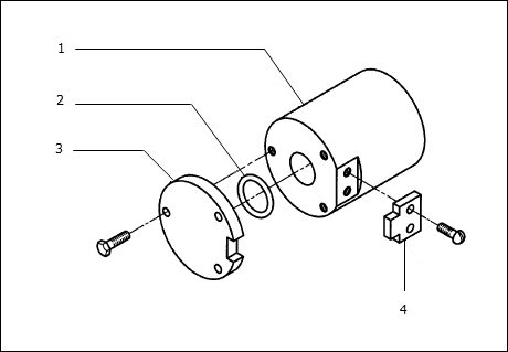
1. Body
2. Seal
3. Cover
4. Key
Now let's step through the process of defining the GD&T for the cover part:
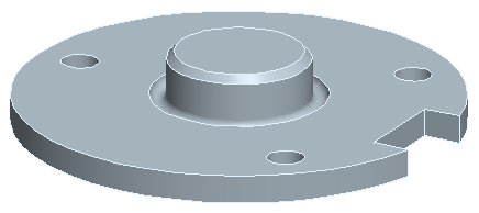
Tutorial
Start up the Application
Open the part file to be used for this tutorial: ...install_folder\Common Files\gdt_home\tutorial_models\cover_ISO.prt.
Start GD&T Advisor by selecting the GD&T Advisor button in the Applications ribbon:
When you start the GD&T Advisor for the first time on a part in which the tolerancing standard is set to ISO/DIN, the Edit Model Properties is displayed:
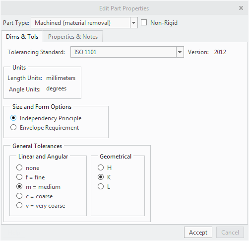
This window displays the properties for the part and allows you to modify certain aspects of those properties.
1. Select Machined (material removal) from the Part Type menu. General linear and angular tolerances are applicable for this part type so those options become enabled.
2. You can leave the general linear and angular tolerances set to m (medium) and general geometrical tolerances set to K.
3. Click Accept in the Edit Model Properties window.
The following messages are listed in the Advisor Tree:
• Not all DOF of the design model are constrained — This message indicates that you have not defined a datum reference frame that is capable of fully immobilizing the part.
• One or more surfaces of the design model are unconstrained — This message is an indication that there are still surfaces for which the limits of variation have not been fully defined.
To get more information about a specific advisor message, either:
1. Double-click on the advisor message.
2. Right-click on the advisor message and select More Help from the drop-down menu.
A help page containing more detailed information about the message in the Creo help system. As you proceed through the modeling process, some advisor messages will be removed from the message list while some new messages may be added to the list. You can double-click on any of those messages to get more information.
Establish the Predominant Datum Reference Frame
The first step in the process of applying GD&T to a part model is to establish the predominant datum reference frame (DRF) that is capable of fully immobilizing the part. It typically references three datums from features used to locate and orient the part within the assembly.
Identify the Primary Datum Feature
The primary datum feature of the predominant DRF typically, but not always, constrains two of the three orientation degrees of freedom of the part within the assembly.
For this part, the best candidate for the primary datum feature is the face contacting the body. If the shaft-like feature was pressed into the body it might be another candidate, but we’ll assume a clearance fit between the two at this interface given the presence of an o-ring seal.
To add the primary datum feature to the model:
1. Click on  (Tolerance Feature) in the GD&T Advisor ribbon. This activates the 'Select' process in Creo.
 (Tolerance Feature) in the GD&T Advisor ribbon. This activates the 'Select' process in Creo.
2. Select the planar surface from the design model and then Accept in the Add Feature dialog window.
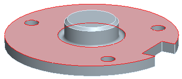
3. The properties of the feature are displayed in the dashboard:

1. Name
2. Scheme
3. Geometric Characteristic Symbol
4. Tolerance value
5. Datum Feature
6. Action buttons
In the dashboard,
a. Specify the feature properties (see Feature Properties):
▪ Name — Enter Mounting Plane for the feature name (See Label #1).
▪ Scheme — Confirm that Geometric Tolerance is selected (See Label #2). The other options are not applicable to the first feature in the model.
▪ Since this is the first feature of the model and general geometrical tolerances are applicable, there is no geometrical tolerance required for this feature. The Segment Control Selector (see Label #3) allows you to add a geometric tolerance (e.g., flatness), but in this case we will not apply any.
c. Specify the datum feature properties (see Datum Feature Properties):
▪ You can accept the default settings (See Label #4). The first feature of a model is always automatically preselected to define a datum if appropriate. Datum features are automatically assigned a label alphabetically, starting with 'A' (although you can override the default label with a user-specified value).
d. Click on  (Accept and close) in the dashboard (See Label #5). Note that the accept button turns green when all required information has been specified in the dashboard.
 (Accept and close) in the dashboard (See Label #5). Note that the accept button turns green when all required information has been specified in the dashboard.
▪ The following data is written to the model and displayed in the GD&T Advisor Feature Tree:
 Mounting Plane Mounting Plane | — A Planar Surface feature |
 Planar Datum A Planar Datum A | — A planar datum that is coplanar to the mounting plane feature |
 A A | — A DRF referencing datum feature A |
▪ An annotation for the datum feature symbol is automatically placed in the CAD model. Note that the datum feature symbol annotation is attached to the point on the surface where you had selected the surface when adding the feature. The annotation is placed on a plane that is perpendicular to the feature plane and is created so that it is readable (from left to right) in the current view.
4. Click on each of the objects in the Feature Tree. Notice that the corresponding object is highlighted in the CAD model. The DRF is represented by a coordinate system – you must turn Csys Display on in order for the coordinate system to highlight when you click on the DRF.
Identify the Secondary Datum Feature
Considering only the primary datum feature (the mounting plane), the part would be free to slide in that plane. The secondary datum feature of the predominant DRF is typically (but not always) the feature that is used to constrain the location of part. In this assembly, the shaft serves that purpose.
To add the secondary datum feature to the model:
1. Click on  (Tolerance Feature) in the GD&T Advisor ribbon. This activates the 'Select' process in Creo.
 (Tolerance Feature) in the GD&T Advisor ribbon. This activates the 'Select' process in Creo.
2. Select the surface of the small shaft from the design model. Note that both surfaces defining the shaft are automatically included in the feature definition.
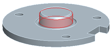
3. Click Accept in the Add Feature dialog window to add the feature.
4. The properties of the feature are displayed in the dashboard:

1. Name
2. Scheme
3. CAD dimension
4. Geometric Characteristic Symbol
5. Tolerance value
6. Material condition modifier
7. Datum feature
8. Action buttons
In the dashboard,
a. Specify the feature properties:
▪ Name — Enter Centering Shaft for the feature name (See Label #1).
▪ Scheme — Select Toleranced Size (See Label #2).
b. Specify the geometric control properties:
▪ The properties for the diameter dimension are read from the CAD dimension (See Label #3). These may be left as-is, or you may select the button to modify the tolerance mode and values. For now, leave the defaults in place.
▪ GD&T Advisor has selected  (Perpendicularity) automatically in the Geometric Characteristic Symbol Selector menu (See Label #4). Notice that when you select the drop-down menu, perpendicularity is represented in the menu with a white-on-green icon, indicating that it is a suggested geometric characteristic symbol. If you hover over one of the options in the menu, you will see a tooltip that provides you with information about the applicability of that geometric characteristic symbol.
 (Perpendicularity) automatically in the Geometric Characteristic Symbol Selector menu (See Label #4). Notice that when you select the drop-down menu, perpendicularity is represented in the menu with a white-on-green icon, indicating that it is a suggested geometric characteristic symbol. If you hover over one of the options in the menu, you will see a tooltip that provides you with information about the applicability of that geometric characteristic symbol.
▪ Specify a value of 0.1 (See Label #5).
▪ Specify Ⓜ (Maximum Material Condition) for the tolerance zonematerial condition modifier (See Label #6). The Help option from that menu provides information to help you decide which modifier to select.
▪ The A DRF is automatically selected.
c. Specify the Datum Feature properties:
▪ Accept the default settings (See Label #7). This feature is automatically set as a datum feature because it is required in order to constrain the part. It is automatically labeled 'B'.
d. Click on  (Accept and close) in the dashboard (See Label #8).
 (Accept and close) in the dashboard (See Label #8).
▪ The following data is written to the model and displayed in the GD&T Advisor Feature Tree:
 Centering Shaft Centering Shaft | — A Shaft feature |
 Axial Datum B Axial Datum B | — An axial datum that is coaxial to the shaft feature |
Ø25.4–25.6 | — The limit dimensions for the diameter (read from CAD model) |
 |Ø0.1(M)|A |Ø0.1(M)|A | — A perpendicularity tolerance applied to the centering shaft feature |
 A|B(M) A|B(M) | — A DRF referencing datum features A and B(M). The (M) modifier is selected for datum feature B by default because you specified Ⓜ for the tolerance zone material condition modifier for the perpendicularity tolerance that is applied to the feature (in step 4b). |
▪ An annotation representing the width dimension, the position tolerance, and the datum feature symbol is automatically placed in the CAD model. In this case, the placement is determined by the placement of the parametric dimension representing the width of the feature.
5. Click on each of the objects in the Feature Tree. Notice that the corresponding object is highlighted in the CAD model.
Identify the Tertiary Datum Feature
The primary and secondary datum features are capable of fully constraining the part in all directions except for rotation about the axis of the shaft. You must select a tertiary datum feature that is suitable for constraining that rotation. Though there are several candidates for a tertiary datum feature in this design, the keyway notch is used to align the orientation of the cover to the body and hence is the recommended feature to use for establishing the tertiary datum.
To add the tertiary datum feature to the model:
1. Click on  (Tolerance Feature) in the GD&T Advisor ribbon. This activates the 'Select' process in Creo.
 (Tolerance Feature) in the GD&T Advisor ribbon. This activates the 'Select' process in Creo.
2. Select one of the planar surfaces of the keyway notch.
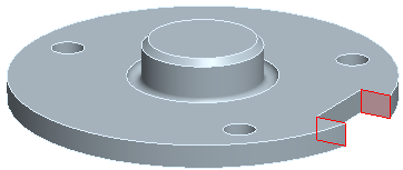
3. Select Slot from the list of candidate features from the combo-box at the top of the Add Feature dialog window.
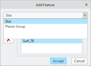
4. Click Accept in the Add Feature dialog window. The properties of the feature are displayed in the dashboard.
5. In the dashboard,
a. Specify the feature properties:
▪ Name — Enter Keyway Notch for the feature name.
▪ Scheme — Select Toleranced Size.
b. Specify the geometric control properties:
▪ The properties for the width dimension of the notch are read from the CAD dimension. There is no need to modify those properties.
▪  (Position) is the only suggested geometrical tolerances for this feature.
 (Position) is the only suggested geometrical tolerances for this feature.
▪ Specify a value of 0.2.
▪ Specify Ⓜ for the Tolerance Zone Material Condition Modifier.
▪ The A|B Ⓜ DRF is automatically selected.
c. Specify the Datum Feature properties:
▪ Just accept the default settings. This feature is automatically set as a datum feature because it is required in order to constrain the part. It is automatically labeled 'C'.
d. Click on  (Accept and close) in the dashboard.
 (Accept and close) in the dashboard.
▪ The following data is written to the model and displayed in the GD&T Advisor Feature Tree:
 Keyway Notch | — A Slot feature |
 Planar Datum C | — A planar datum located at the mid-plane of the feature |
 18.0–19.0 | — The limit dimensions for the width of the slot feature (read from CAD model) |
 |Ø0.2(M)|A|B(M) | — A position tolerance applied to the keyway notch feature |
 Planar Surface 2 | — Planar surface features representing each plane |
 Planar Surface 3 | |
 A|B(M)|C(M) | — A DRF referencing datum features A, B(M), and C(M). The (M) modifier is selected for datum feature C by default because you specified Ⓜ for the tolerance zone material condition modifier for the position tolerance that is applied to the feature (in step 5b). |
▪ An annotation representing the width dimension, the position tolerance, and the datum feature symbol is automatically placed in the CAD model. In this case, the placement is determined by the placement of the parametric dimension representing the width of the feature.
The A|B(M)|C(M) DRF is the first fully constrained DRF in the model. Thus it is considered the predominant datum reference frame.
Show Constraint State Display
At any time during the process, you can select the Show/Hide Constraint State button ( ) to color-code the surfaces based on their constraint state:
 ) to color-code the surfaces based on their constraint state:
1. Click on  (Show/Hide Constraint State) in the toolbar to see the constraint state of the part surfaces. A legend is displayed at the bottom of the Feature Tree that shows the meaning of the colors for this display. In this case, the surfaces referenced by the features that you have defined so far are green, indicating that they are fully constrained. The gray surfaces are unconstrained because they are not referenced by any GD&T Advisor features.
 (Show/Hide Constraint State) in the toolbar to see the constraint state of the part surfaces. A legend is displayed at the bottom of the Feature Tree that shows the meaning of the colors for this display. In this case, the surfaces referenced by the features that you have defined so far are green, indicating that they are fully constrained. The gray surfaces are unconstrained because they are not referenced by any GD&T Advisor features.
You can leave this button selected and continue to define GD&T on additional features (however if you do so, your model appearance will differ from the pictures in this document). See Constraint State Display for more information about this display option.
Complete the GD&T Scheme for the Model
Add the Pattern of Holes
Now that the predominant DRF has been established, the next step is to identify other features in the model and constrain those features to the predominant datum reference frame. In complex parts, it may be necessary to establish other auxiliary DRFs, but ultimately all features must be constrained, either directly or indirectly, to the predominant DRF.
For features that are constrained to the same DRF, the order in which you add them to the model is not important.
1. Click on  (Tolerance Feature) in the GD&T Advisor ribbon. This activates the 'Select' process in Creo.
 (Tolerance Feature) in the GD&T Advisor ribbon. This activates the 'Select' process in Creo.
2. Select one of the surfaces from one of the holes in the pattern. The Add Feature window is displayed and a Simple Hole feature is defined based on the selected surface. Notice that the 'Add entire pattern' check box is automatically selected because the application recognizes that hole feature is part of a pattern in the CAD model.
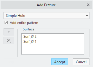
3. Click Accept in the Add Feature dialog window. The properties of the pattern are displayed in the dashboard.
4. In the dashboard,
a. Specify the pattern properties:
▪ Name — Enter Fastener Holes for the pattern name.
b. Specify the geometric control properties:
▪ The properties for the diameter dimension are read from the CAD dimension.
▪  (Position) is the only applicable geometrical tolerances for the pattern.
 (Position) is the only applicable geometrical tolerances for the pattern.
▪ Specify a value of 0.2.
▪ Specify Ⓜ for the Tolerance Zone Material Condition Modifier.
▪ The A|BⓂ|CⓂ DRF is automatically selected. Click on the Datum Reference Frame Selector to see the other available DRFs. The DRF menu is filtered to only include DRFs that are applicable for the feature/pattern and a recommended DRF is selected by default. The Help option from that menu provides information to help you decide which DRF to select.
c. Specify the Datum Feature properties:
▪ Notice that the Datum Feature check box is not selected by default because there is already a fully constrained DRF defined in the model.
▪ Leave Datum Feature unselected.
d. Click on  (Accept and close) in the dashboard.
 (Accept and close) in the dashboard.
▪ A linked pattern of Hole features is added to the GD&T Advisor model.
▪ An annotation is automatically placed in the CAD model.
A linked pattern, indicated by a  superimposed over the pattern icon (e.g.,
 ), is directly associated with a feature pattern in the CAD model. If you change the pattern properties in the CAD model (e.g., change the number of holes) the linked pattern in the GD&T Advisor model will update automatically.
 superimposed over the pattern icon (e.g.,
 ), is directly associated with a feature pattern in the CAD model. If you change the pattern properties in the CAD model (e.g., change the number of holes) the linked pattern in the GD&T Advisor model will update automatically.
There is also a Tolerance Pattern button ( ) in the GD&T Advisor ribbon. That function is used to add a pattern of features that may not have been created as a pattern in the CAD model. For example, you could have created the fastener holes in this part as a single extruded cut in the CAD model (with three equal-sized circles in the sketch). If the holes were created in that manner, they would not be automatically recognized as a pattern, but you could add them to the model as a pattern with the Add Pattern button. However, they would be added as an 'unlinked' pattern, meaning that if you changed the number of holes (e.g., modified the sketch by adding another circle), the pattern in the GD&T Advisor model would not update automatically, although you could edit the pattern and add the other hole to it.
 ) in the GD&T Advisor ribbon. That function is used to add a pattern of features that may not have been created as a pattern in the CAD model. For example, you could have created the fastener holes in this part as a single extruded cut in the CAD model (with three equal-sized circles in the sketch). If the holes were created in that manner, they would not be automatically recognized as a pattern, but you could add them to the model as a pattern with the Add Pattern button. However, they would be added as an 'unlinked' pattern, meaning that if you changed the number of holes (e.g., modified the sketch by adding another circle), the pattern in the GD&T Advisor model would not update automatically, although you could edit the pattern and add the other hole to it.
Annotation Modification
The annotation plane is automatically determined based on the feature type and the current view orientation. The leader attachment is at the point where you picked when you selected the surface when adding the feature. GD&T Advisor creates native Creo annotations. You can use native Creo functionality to change the annotation plane, move the annotation, or modify the leader attachment point.
1. Use native Creo functionality to arrange the annotations on the model as desired.
You can also modify the tolerance value as you normally would in Creo, but you should only modify other aspects of the geometrical tolerance through the GD&T Advisor application. If the geometrical tolerance is modified using the native Creo tools, those changes are evaluated whenever the GD&T Advisor does a 'model update'. The 'model update' process runs under the following conditions:
• At GD&T Advisor startup.
• When GD&T Advisor is running and model is regenerated.
• When Update is selected from the GD&T Advisor ribbon.
The 'model update' process synchronizes the GD&T Advisor data with the Creo model data. When there are synchronization problems, those problems are either automatically repaired (if possible) or an advisor message indicating the problem is displayed. For more information about the 'model update' process, see User Interface and Workflow.
Add a General Note for a Default Tolerance
There are often features in the model which are not critical to the function of the part. However, in most cases it is necessary to define the limits of variation for ALL features of the design model. For the non-critical features, you may want to specify a general default tolerance in a note. To do so:
1. Click on  Edit Properties... in the GD&T Advisor ribbon launch the Edit Model Properties window.
 Edit Properties... in the GD&T Advisor ribbon launch the Edit Model Properties window.
2. Click on the Properties & Notes tab in the Edit Model Properties window. This interface allows you to manage the general notes that get added to the model. Click on the Help button on this window to get more information.
3. Click on General Profile in the 'Not Displayed' list on the right side of the window, and then click the Select button ( ) to move that note to the 'Displayed' list.
 ) to move that note to the 'Displayed' list.
4. Click on General Profile in the 'Displayed' list. A preview of the note text is shown at in the lower portion of the window. Notice that the note includes a variable named 'Tolerance'. The properties for that variable are displayed above the Note Text. In this case, the variable requires a real number.
5. Enter a value of 0.3 for the tolerance variable and then click Accept.
◦ A note specifying the general surface profile is placed in the upper left corner of the screen. Notice that the surface profile automatically references the predominant DRF.
◦ The color of all of the surfaces that are not referenced by a GD&T Advisor feature is changed to blue (assuming Constraint State Display is on), indicating that those surfaces are constrained by the general surface profile.
◦ The message indicating that some surfaces have not been constrained is removed from the Advisor Tree.
There are no longer any messages shown in the Advisor Tree, indicating that you have defined a complete and valid GD&T scheme for this design model. However, the design may require that you specify the tolerances on some of the unspecified surfaces explicitly.
Add the Top Plane of the Cover
1. Click on  (Tolerance Feature) in the GD&T Advisor ribbon to activate the 'Select' process in Creo.
 (Tolerance Feature) in the GD&T Advisor ribbon to activate the 'Select' process in Creo.
2. Select the planar surface that is opposing the Mounting Plane (datum feature A) and then Accept in the Add Feature dialog window. The properties of the feature are displayed in the dashboard.
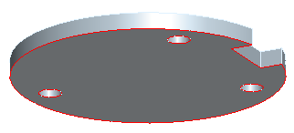
3. In the dashboard,
a. Specify the feature properties.
▪ Name — Enter Top Plane for the feature name.
▪ Scheme — Select Size Dimension. Notice that 'Please select dimensions' is shown underneath the scheme combo-box. You must select the size dimension from the CAD model.
1. Click on Dimension panel header along the lower edge of the dashboard to view the dimension panel. This panel displays a list of all of the required dimensions. In this case there is only a 'Width' dimension required.
2. Click on the Auto Match button to have the model automatically search the model for an applicable dimension. Notice that the properties of the dimension update in the table, indicating that an applicable dimension and reference feature were found.
3. Click on the 5 button in the Value column to launch the Edit Dimension window.
4. Select + / - Symmetric for the tolerance model and specify a toleranced value of ±0.1 and click Accept in the Edit Dimension window.
5. Click on the Dimension panel header again to close the panel.
b. No geometrical tolerances are required for this feature.
c. Leave the Datum Feature check box unselected.
d. Click on  (Accept and close) in the dashboard.
 (Accept and close) in the dashboard.
▪ A Planar Surface feature is added to the GD&T Advisor model and the constraint state display is updated.
▪ An annotation is automatically placed in the CAD model.
The placement of this annotation is dependent on the location of the parametric dimension in the model. Sometimes the dimension is placed within the part, making it difficult to see. If you click on the dimension in the Feature Tree, it will highlight in the CAD model. If you want to move the dimension, you can do so using the native tools in the CAD system.
Add the End Plane of the Shaft
1. Click on  (Tolerance Feature) in the GD&T Advisor ribbon to activate the 'Select' process in Creo.
 (Tolerance Feature) in the GD&T Advisor ribbon to activate the 'Select' process in Creo.
2. Select the end plane of the Center Shaft and then Accept in the Add Feature dialog window. The properties of the feature are displayed in the dashboard.
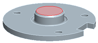
3. In the dashboard...
a. Specify the feature properties.
▪ Name — Enter Shaft End Plane for the feature name.
▪ Scheme — Select Offset Dimension. Notice that 'Please select dimensions' is shown underneath the scheme combo-box. You must select the offset dimension from the CAD model. (This is a good time to discuss the difference between 'Size Dimension' and 'Offset Dimension': A size dimension defines the width between parallel, opposed, and overlapping planar features. The two parallel planes comprise a feature of size, so the envelope requirement may be applicable. An offset dimension is used to define the distance between parallel planes that are not opposed or are not overlapping. The envelope requirement may not be applied because no feature of size is defined. In order to differentiate an offset dimension from a size dimension, 'OFFSET' is added to the dimension annotation.)
1. Click on Dimension panel header along the lower edge of the dashboard to view the dimension panel. This panel displays a list of all of the required dimensions. In this case there is only a 'Offset' dimension required.
2. Click on the Auto Match button to have the model automatically search the model for an applicable dimension. Notice that the properties of the dimension update in the table, indicating that an applicable dimension was found.
3. Click on the 8 button in the Value column to launch the Edit Dimension window.
4. Select + / - Symmetric for the tolerance model and specify a toleranced value of ±0.1 and click Accept in the Edit Dimension window.
5. Click on the Dimension panel header again to close the panel.
b. No geometrical tolerances are required for this feature.
c. Leave the Datum Feature unselected.
d. Click on  (Accept and close) in the dashboard.
 (Accept and close) in the dashboard.
▪ A Planar Surface feature is added to the GD&T Advisor model and the constraint state display is updated.
▪ An annotation is automatically placed in the CAD model.
The other surfaces in this part are not critical, so the surface profile in the general note is sufficient for those surfaces. You have now completed the GD&T scheme for this part in accordance with the ISO GPS standards.
Save the Part
You can save the Creo part as you normally would. There is no additional GD&T Advisor data file to manage – all GD&T Advisor data is stored within the part file.