User-defined datums
GD&T Advisor directly supports establishing a datum axis or datum plane from datum targets. However, those targets are limited to either point or line targets (see Datums from Targets). For cases that are not directly supported (e.g., area targets, equalizing targets, etc.), you can use user-defined datums.
With a user-defined datum, you can associate a datum plane or a datum axis with a feature in GD&T Advisor, and then define the targets in Creo as needed.
The examples below describe some common uses for user-defined datums.
Establishing a datum plane from 3 area targets
Area targets are commonly used for establishing datum planes. You can use the process described here for establishing a datum plane from 3 circular area targets.
1. Create a Creo datum plane that is parallel to (or coplanar with) the planar surface.
2. In Creo, create datum points at the target locations on the planar surfaces.
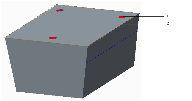
1. Sketched area targets
2. Datum plane
3. In GD&T Advisor, click on  (Tolerance Feature) in the GD&T Advisor ribbon and select the planar surface.
(Tolerance Feature) in the GD&T Advisor ribbon and select the planar surface.a. In the Add Feature dashboard, select the Datum from Targets check box (see Datum Feature Properties).
b. Open the Targets slide-out panel in the dashboard (see Targets Slide-out Panel).
a. Select User-defined Plane from the Type Selector menu.
b. Click on the Plane Selector button.
c. Select the datum plane in the Creo model.
c. Click on  (Accept and close) in the dashboard.
(Accept and close) in the dashboard.Planar Surface 1 is added to the model, along with Planar Datum A - a user-defined datum plane. The Advisor Tree shows this message: 'User-defined datum requires datum targets'. You must define the targets for the datum plane. Double-click on that message for more information.
4. Use Creo functionality to create the datum targets on the Annotate ribbon:
a. Select a suitable annotation plane.
b. Select the Datum Target button. Select a datum point on the feature surface and then click the middle mouse button to place the datum target annotation.
c. In the Datum Target dashboard:
a. Select Circle for the Target Area
b. Specify the diameter value for the target area
c. Specify the datum reference and relevant index (e.g., A1)
d. Repeat steps 4a-4d for the other two targets.
Note that after completing this process, the 'User-defined datum requires datum targets' message will continue to be displayed for the datum until the application performs the next model update, as described in UI and Workflow.
When using user-defined datums, keep in mind it is up to you to make sure you have followed the rules established in the tolerancing standards. GD&T Advisor does not perform any tests to ensure that you have established and referenced the user-defined datum correctly. You should consider the following:
• You must reference a datum from targets with a fully constrained datum reference frame in order to fully constrain the locations of the datum targets.
• You should create basic locating dimensions from the fully constrained datum reference frame to each of the datum targets.
Refer to the applicable tolerancing standard for more information about datum targets.
Establishing a datum plane from equalizing targets
Equalizing datum targets are commonly used to establish a datum plane that is centered on the feature associated with the targets. In the model pictured below, the central datum plane may be established with the indicated equalizing line targets.
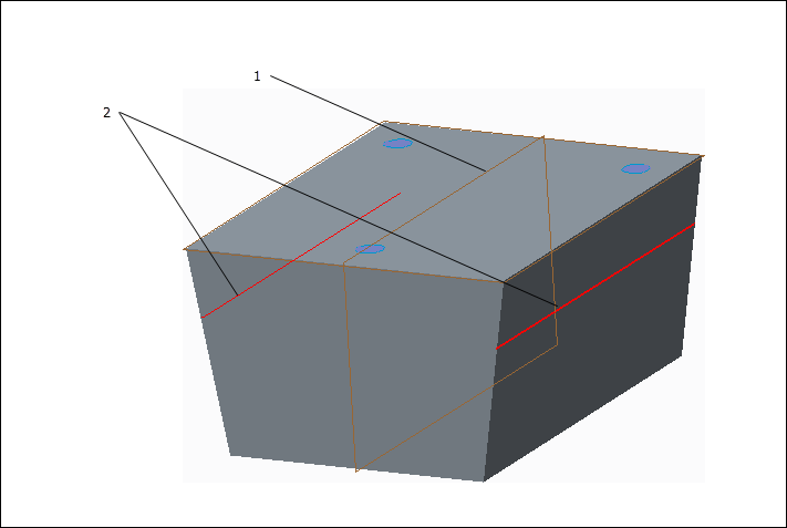
1. Datum Plane
2. Equalizing targets
The process for establishing this datum plane in GD&T Advisor is very similar to the process described above. You should consider the following when including the datum plane in the model:
• All datum targets used to establish a datum must be associated with the same feature. In this case, you must include the two planar surfaces in the feature definition (a Tapered Slab feature).
• You should make sure to select the applicable datum target symbol type in Creo. In this case, you should use the None TARGET Area option.
• In this example, the datum plane is the secondary reference in the predominant datum reference frame. The datum plane must be perpendicular to the primary plane.
• You must reference a datum from targets with a fully constrained datum reference frame in order to fully constrain the locations of the datum targets.
• You should create basic locating dimensions from the fully constrained datum reference frame to each of the datum targets.
Refer to the applicable tolerancing standard for more information about datum targets.