Edit Model Properties
General Properties
Part Type
The part type is used to determine the applicability of general linear and angular tolerances that reference the ISO 1101 tolerancing standard.
Non-Rigid
This option indicates that the part should be considered a non-rigid part. A non-rigid part is a part that deforms to an extent that in the free state it is beyond the specified dimensional and or geometric tolerances.
When selected, the application automatically includes a general note (see Properties and Notes) describing the restraint conditions for verifying the part requirements. Geometric tolerances that are to be verified in the free state should include the free state symbol Ⓕ in the feature control frame. In addition, when the part references the ISO 1101 tolerancing standard, a note is automatically added to the model indicating that ISO 10579 is invoked.
Dims & Tols
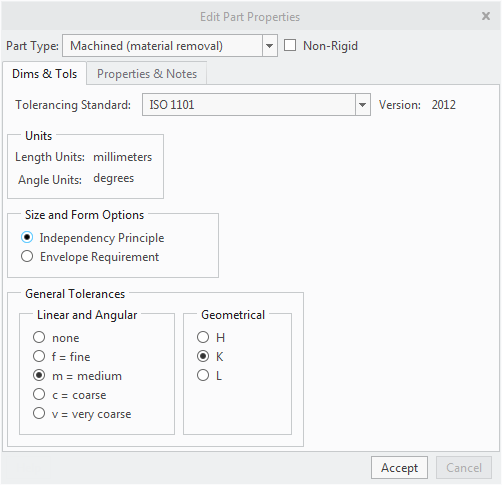
Tolerancing Standard
The tolerancing standard property is initialized from tolerance standard property in the CAD model. The supported tolerancing standards are:
• ASME Y14.5-2009
• ASME Y14.5-2018
• ISO 1101:2012
• ISO 1101:2017
The application automatically adds notes referencing the applicable standards. See Standards Reference Notes (ASME), Standards Reference Notes (ISO), or Standards Reference Notes DIN for more information.
Units
This section shows the units used for linear and angular dimensions in the model. The application automatically adds a note indicating the linear units for the model (as required by both the ASME and ISO standards).
Size and Form Options
The size and form options are only applicable to the ISO 1101 tolerancing standard. These options are disabled if ASME Y14.5 is the referenced standard.
Independency Principle
The independency principle states that each specified dimensional or geometric requirement shall be met independently, unless a particular relationship is specified (i.e., MMR, LMR, or envelope requirement). Where no relationship is specified, a geometrical tolerance applies regardless of feature size, and the two requirements (size and geometrical) are independent. This means size and form, size and orientation, or size and location are independent requirements and affect (or define) the extreme boundary of the feature of size.
Envelope Requirement
The envelope requirement is one way to specify a requirement for mutual dependency between dimensional tolerances (size) and geometrical tolerances (form). The envelope requirement states that a feature of size cannot violate the envelope of perfect form at maximum material size. For example, if all actual local diameters of a shaft feature are at their maximum size, the shaft feature must be perfectly cylindrical.
Where ISO 8015 is referenced, the principle of independency is invoked by default and requires that ISO 2768 is also invoked in order to specify the applicable general tolerances. Selecting the Envelope Requirement option includes the "E" suffix for the reference to ISO 2768 (e.g., ISO 2768-mH-E), indicating that the envelope requirement becomes the default condition for features of size.
Remember, if the default condition is the independency principle, the envelope requirement can be invoked for individual features of size by indicating the Ⓔ symbol next to the dimension.
Knowing when to use the independency principle or envelope requirement can be confusing. Generally, the envelope rule should be used when a feature of size assembles with another feature of size. This ensures assembly at worst case and allows the maximum tolerances for manufacturing. When a feature of size does not assemble with another feature of size, the independency principle should be considered.
General Tolerances
The general tolerances options are only applicable to the ISO 1101 tolerancing standard. These options are disabled if ASME Y14.5 is the referenced standard.
Linear and Angular
The setting specifies the tolerance class for general tolerances for linear and angular dimensions and is initialized from model class property in the CAD model. When you change the tolerance class designation in GD&T Advisor, the model class property is automatically updated in the CAD model (and vice versa). ISO 2768-1 includes tables of values for permissible deviations for linear and angular dimensions based on the tolerance class designation and dimension value.
According to ISO 2768-1, general tolerances for linear and angular dimensions are only applicable for parts that are produced by metal removal or parts that are formed from sheet metal. Thus, if the part type is set to 'Other', the general tolerance for linear and angular dimensions is set to 'none' and may not be modified.
Geometrical
The setting specifies the tolerance class for general geometrical tolerances. ISO 2768-2 includes tables for general tolerances based on the tolerance class and the extents of the applicable feature.
According to ISO 2768-2, 'unless otherwise stated, workpieces exceeding the general geometrical tolerance shall not lead to automatic rejection provided that the ability of the workpiece to function is not impaired.' Thus, unlike geometrical tolerances that are explicitly indicated, general geometrical tolerances do not define requirements for the part. Furthermore, the interpretation of general geometrical tolerances that require a reference (e.g., perpendicularity, etc.) is ambiguous. Thus, when evaluating the constraint state of a surface, GD&T Advisor considers only general geometrical tolerances for form (i.e., flatness, straightness, roundness, and cylindricity). Other general geometrical tolerances are ignored for the constraint state evaluation.
Properties & Notes
This tab of the Edit Model Properties window provides an interface for managing the general notes for the model. There are three sources for the available notes:
• Predefined Application Notes – notes that are predefined in the application. See Predefined Application Notes (ASME)for more information.
• Administrator-defined Notes – notes that have been defined by the application administrator. See Application Options for more information.
• User-defined Notes– notes that are defined by the user for a specific model.
The user interface includes two list regions, Displayed and Not Displayed, that enable you to manage the visibility of the notes. Note that some application or administrator notes may be required. A required note must be displayed – you cannot move required notes to the 'Not Displayed' list. For example, if you have indicated that the part is non-rigid, there is a Non-rigid Part note that is added to the Displayed list. This is a required note for non-rigid parts and must be displayed as long as the 'non-rigid' check box is selected.
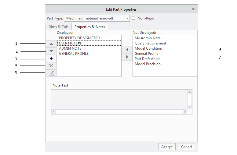
1. Move up — Move the selected note up in the Display list. Notes are displayed on the model in the order specified.
2. Move down — Move the selected note down in the Display list.
3. Add a user-defined note — Launch the Add/edit Note window to define a user-defined note for the part.
4. Delete a user-defined note — Delete the selected user-defined note. This option is disabled unless a user-defined note has been selected.
5. Edit a user-defined note — Launch the Add/edit Note window to edit the selected user-defined note. This option is disabled unless a user-defined note has been selected.
6. Select — Move the selected note to the Displayed: list.
7. Unselect — Move the selected note to the Not Displayed: list.
Notes may include a variable and its value. A variable may be one of the following types:
• Integer number
• Real number
• String
• Parameter ID
For example, the 'General Profile' note includes a real-number variable named 'Tolerance'. When 'General Tolerance' is in the 'Displayed' list, you must specify a value for 'Tolerance' that is compatible with the variable type. If the variable type is 'Parameter ID', you must specify the name of a parameter or dimension ID (e.g., d11) that exists in the CAD model.
Once you have specified the desired notes in the 'Display' list and click the Accept button, the application generates the specified notes in the order shown in the 'Display' list. You can control the order of the list with the 'Move up' and 'Move down' arrows to the left of the 'Display' list.